| Field | Data |
|---|---|
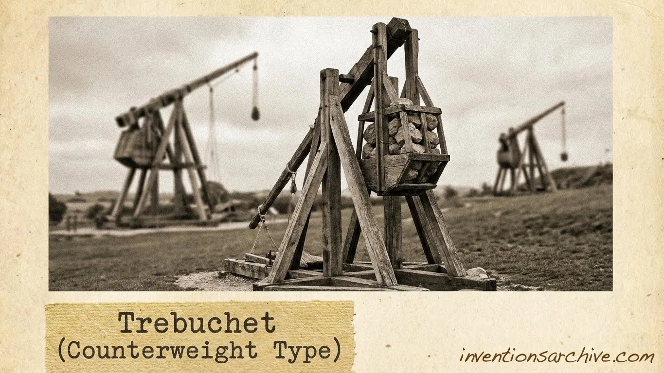
| Invention Name | Trebuchet (counterweight type) |
| Short Definition | Gravity-driven lever launcher with a sling |
| Approximate Date / Period | Mid–Late 12th Century Approx. |
| Date Certainty | Approximate (first clear records vary) |
| Geography | Mediterranean (Eastern & Western regions) |
| Inventor / Source Culture | Anonymous / collective (multi-region engineering tradition) |
| Category | Mechanical Engineering; fortification technology |
| Need / Driver | Higher repeatability; greater energy storage |
| How It Works | Potential energy → rotational motion → sling release |
| Materials / Tech Basis | Timber frames; iron fittings; rope; counterweight box |
| Early Use Context | Large-scale lifting & launching (documented in medieval technical writing) |
| Spread Route | Mediterranean → broader Europe → other regions |
| Derived Developments | Hinged counterweight; propped counterweight; floating-arm variants |
| Impact Areas | Engineering; materials practice; measurement; mechanics education |
| Debates / Different Views | Contested “first” location; diffusion vs. parallel invention |
| Precursors + Successors | Traction trebuchets → counterweight trebuchets → later mechanical launchers |
| Key Traditions | Medieval technical manuscripts; early modern engineering books |
| Influenced Variations | Fixed; hanging; hinged; hybrid; floating-arm |
Counterweight trebuchets are among the clearest examples of medieval mechanical reasoning made visible at full scale. The machine is simple to describe—a lever, a weight, a sling—yet its behavior depends on timing, stiffness, friction, and the geometry of moving parts.
Table Of Contents
What The Counterweight Trebuchet Is
A counterweight trebuchet is a compound machine that uses gravity as its power source. A heavy mass is raised and held, storing potential energy. When released, that energy drives a rotating beam; the far end accelerates a sling, which releases its load at a controlled moment.
- Power source: falling mass (not twisted cords, not a spring)
- Amplifier: long lever arm plus sling extension
- Control point: release geometry (pin/hook and sling loop)
In museum terms, it sits at a crossroads: carpentry, rope craft, and applied mechanics meet in one object. The design rewards careful proportioning and stable construction, because the machine’s motion is fast and the forces are not gentle.
Origins and Timeline
Counterweight designs appear in the historical record as part of a wider family of lever-and-sling launchers. Earlier traditions relied on teams pulling ropes (often called traction systems). The counterweight form replaces variable human input with a repeatable falling mass, shifting the engineering challenge toward geometry, structure, and timing.
Milestones In The Record
- Traction phase: rope-pulled machines dominate early descriptions in several regions.
- Counterweight shift: gravity-powered forms become visible in the Mediterranean world by the 12th century Details
- Refinement: designs diversify into fixed, hanging, and hinged counterweights, with later tweaks to reduce stress and improve smoothness.
- Early modern documentation: engineering books and prints preserve mature forms with labeled parts and mechanisms.
When historians talk about “invention” here, they rarely mean a single workshop moment. The evidence points to incremental design change—new joints, new ways to hang a mass, new approaches to the sling—each small on paper, each major in motion.
Core Parts and Materials
Structural Elements
- Base and trestle frame for stability
- Axle supports rotation and alignment
- Main beam (throwing arm + short arm)
- Bracing to limit racking and sway
Motion and Control
- Counterweight box or hopper (often stone, sand, metal)
- Hanger or hinge (in many later forms)
- Sling with a loop and release cord
- Release pin (timing the sling opening)
- Winch and holding catch in many large examples
| Part | Engineering Role | Why It Matters |
|---|---|---|
| Axle + bearings | Low-friction rotation | Energy retention and consistent motion |
| Beam stiffness | Controls flex | Repeatable release; reduced vibration |
| Sling geometry | Extends effective radius | Higher tip speed with controlled timing |
| Counterweight linkage | Sets weight path | Smoother acceleration when the drop is closer to vertical |
How The Mechanism Works
A counterweight trebuchet is a study in energy conversion. At the start, the system stores gravitational potential energy in the raised mass. In simplified analysis, that energy can be treated as U ≈ mgh, then tracked as it becomes rotational and translational motion Details.
A Typical Motion Sequence
- Energy storage: the counterweight is held high; the beam is drawn into a starting position.
- Acceleration: the mass drops; the short arm descends; the long arm swings upward, building speed.
- Sling extension: the sling trails, then tightens, increasing the effective radius and tip velocity.
- Release: the sling loop slips free at a specific angle, sending the load along a tangent path.
Two motions happen at once: the beam rotates and the sling pivots. That interaction is why the same machine can feel predictable in one setup and erratic in another. Small differences in friction, slack, or flex can shift the release timing more than a casual observer expects.
Many later designs prefer a hinged counterweight because the mass can descend in a path closer to a straight drop, which tends to improve how effectively gravity does work on the system Details. In engineering terms, it is an effort to reduce wasted motion and soften peak loads at the end of the swing.
Types and Variations
The label “counterweight trebuchet” covers a family of related machines. Their shared idea is gravity plus a lever, yet the counterweight attachment and the sling arrangement create distinct behaviors.
| Variant | Signature Feature | Engineering Effect |
|---|---|---|
| Fixed counterweight | Weight rigidly connected to short arm | Simple build; more arc-like weight path |
| Hanging counterweight | Weight suspended below short arm | Smoother fall; less abrupt rotation of the mass |
| Hinged counterweight | Weight on a pivoting hanger | Closer-to-vertical descent; reduced peak stress |
| Propped counterweight | Weight begins at a tilted angle | Extra drop distance; altered acceleration profile |
| Hybrid forms | Combined inputs (weight + assisted pull) | Transitional solutions in some traditions |
| Floating-arm variants | Arm geometry changes the sling path | Different release dynamics; compact layouts in some reconstructions |
Engineering Choices That Shape Performance
From an engineering viewpoint, the machine’s results come from constraints, not magic. The most influential factors typically sit in four categories: geometry, mass distribution, losses, and release timing.
Geometry
- Axle height relative to the base
- Arm lengths and where the sling attaches
- Sling length and symmetry
Mass and Losses
- Counterweight mass and how it moves
- Beam inertia and unwanted flex
- Friction at the axle and in rope elements
The sling’s release is the machine’s most delicate moment. The loop must disengage cleanly so the outgoing path is consistent. In practice, the release geometry acts like a timing gate: it determines when the sling stops following the arm and begins a free trajectory. That single instant shapes the visible outcome more than many larger-looking parts.
Evidence In Texts and Images
Counterweight trebuchets are unusually well served by visual documentation compared with many medieval technologies. Drawings and diagrams capture relationships—beam position, counterweight housing, trigger placement—that are hard to infer from words alone. The images are not always scale-accurate, yet they preserve design intent.
Why An Early Modern Plate Matters
Agostino Ramelli’s printed engineering work includes a counterweight trebuchet plate dated 1588, presented with mechanical notes such as winch and trigger. Even when the intended use differs from earlier medieval contexts, such plates show how a mature mechanism could be communicated across readers and workshops Details.
Legacy In Engineering and Education
The counterweight trebuchet remains a compact teaching object for classical mechanics. It naturally connects potential energy, rotational inertia, coupled pendulum-like motion, and the idea that real machines lose energy through friction and deformation. The mechanism’s appeal is that it looks straightforward, then rewards deeper analysis.
- Energy accounting: where mgh goes, and what portion appears as motion
- Coupled dynamics: beam rotation plus sling pivot
- Design interpretation: how drawings encode function without modern notation
Frequently Asked Questions
What makes a counterweight trebuchet different from a traction trebuchet?
Traction machines use people pulling ropes as the driving input. A counterweight trebuchet replaces that with a falling mass, which usually increases repeatability and shifts the main engineering problem toward structure and timing.
Why does the sling matter so much?
The sling increases the effective radius of the moving end of the arm, which can raise tip speed. It also acts as a timing mechanism—release occurs when the loop disengages, not simply when the beam reaches a fixed angle.
What is the practical difference between fixed and hinged counterweights?
A fixed counterweight follows an arc with the arm. A hinged counterweight can descend in a path closer to a vertical drop, often producing smoother acceleration and lower peak loads at the end of the swing.
Do historical sources agree on where the counterweight type first appeared?
Not fully. Many discussions emphasize the Mediterranean in the 12th century, while the exact “first” setting remains debated because records and terminology vary across regions.
Why do museums and researchers still study trebuchets today?
They provide a clear window into pre-modern engineering practice: large timber structures, rope technology, joint design, and empirical tuning. The device also serves as a vivid case study for mechanics in education and public interpretation.