
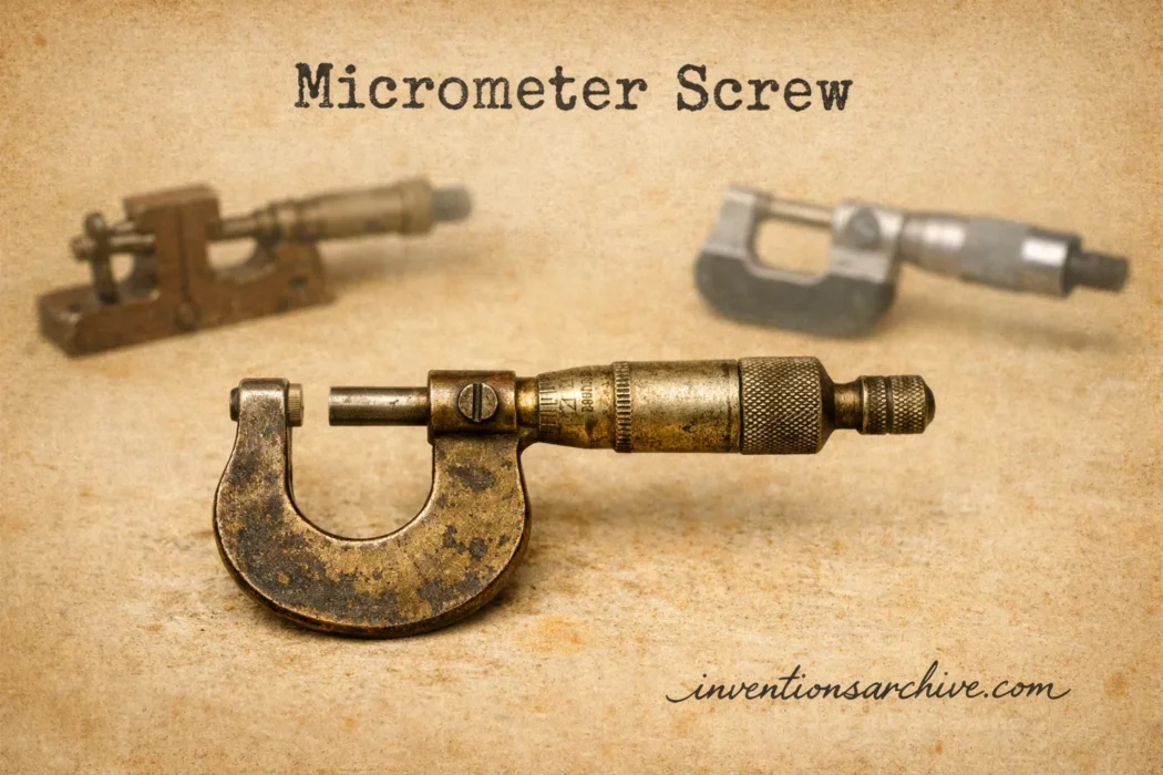
| Invention Name | Micrometer Screw |
|---|---|
| Short Definition | A finely threaded screw used to convert controlled rotation into very small, measurable linear movement. |
| Approximate Date or Period | Documented examples from the early 17th century; astronomical use by about 1639; workshop forms developed during the 18th and 19th centuries. |
| Geography | Dresden in Saxony; later England, France, and the United States. |
| Inventor or Source Culture | No single inventor. Early evidence is associated with Christoph Trechsler and Dresden instrument making; William Gascoigne is closely associated with the astronomical micrometer. |
| Category | Precision measurement, metrology, scientific instruments, machine tools. |
| Importance | Allowed small distances to be derived from screw rotation instead of relying only on directly engraved linear scales. |
| Evidence Status | Multiple documented development stages |
| Main Problem Solved | Controlled measurement and positioning at scales too fine for convenient direct reading. |
| Development Path | Precision instrument screws → astronomical micrometers → end and bench measuring machines → handheld micrometer calipers. |
| Technical Principle | Known screw pitch converts angular rotation into predictable axial displacement. |
| Modern Descendants | Outside, inside, depth, bench, differential, mechanical, and digital micrometers. |
From Fine Adjustment to Measured Displacement
The micrometer screw is easier to understand as a mechanism than as a single finished invention. A normal screw already converts rotation into linear movement: turn it through its mating thread and it advances or retreats along its axis. Instrument makers discovered that a carefully made screw could do something more useful. If its pitch was known and its rotation could be divided on a graduated scale, the screw itself became a means of measuring distances far smaller than the divisions that could conveniently be engraved on a straight ruler.
This idea appeared before the familiar U-shaped micrometer used in machine shops. Early micrometer screws belonged to mathematical and astronomical instruments, where they positioned pointers, sights, wires, or other components by tiny controlled amounts. The modern measuring caliper emerged only after this principle had passed through several generations of scientific and workshop instrumentation.
The Earliest Surviving Evidence Comes from Instrument Makers
Research into surviving European mathematical instruments pushes documented micrometer-screw mechanisms into the early seventeenth century. A study published by The Metropolitan Museum of Art examined precision instruments associated with the Dresden maker Christoph Trechsler the Elder. Among the evidence are finely made instruments in which a screw moves a cursor while a circular graduated scale records fractions of the screw’s rotation.[a]
The dating is important because the history is not as simple as assigning the micrometer screw to one inventor on one day. A precision ruler connected with the mathematician Lucas Brunn carried dates associated with 1609 and 1619, and its micrometer adjustments have been cited as some of the earliest known examples. The study also discusses beam compasses with micrometer-screw adjustment made by Trechsler. The Metropolitan Museum preserves a brass beam compass dated 1619, while another related example is dated 1616.[b]
On the Met’s beam compass, a finely threaded screw moves one of the pointed cursors along the beam. A graduated disk attached to the screw subdivides its rotation. The mechanism therefore joins two ideas that define later micrometers: a screw supplies controlled linear displacement, and a circular scale turns that displacement into readable measurement.
These instruments were not handheld micrometer calipers. Their existence instead shows that the micrometer-screw principle developed within precision mathematical instrument making before its better-known astronomical and industrial applications.
Gascoigne Put Micrometric Measurement Inside the Telescope
William Gascoigne, an English astronomer and instrument experimenter, gave the screw a new role in precision astronomy. Royal Society records state that Gascoigne had applied a micrometer in the optical path of a telescope for measuring small angles by 1639.[c]
Instead of trying to estimate a planet’s apparent diameter against a coarse external scale, an observer could place movable reference points or fine lines in the telescope’s focal plane. Turning a precisely threaded screw changed their separation by a known amount. Once the screw displacement and optical geometry were understood, small angular separations could be calculated from the measured movement.
This transformed the screw from a mechanical adjustment into part of an observational measuring system. Fine rotation outside the telescope produced extremely small controlled displacement where the astronomical image was being examined.
Gascoigne died in 1644, before his work was widely circulated. His micrometer therefore did not immediately become a standard European astronomical instrument. The surviving historical record became much clearer more than two decades later, when a dispute over priority brought the English design before the Royal Society.
The 1667 Priority Dispute Preserved the Astronomical Design
In the 1660s, French astronomers were also working on methods for measuring extremely small angles. An account connected with Adrien Auzout prompted Richard Towneley to inform the Royal Society that Gascoigne had already used such a device before the English Civil War.
The Royal Society archive records Towneley’s claim and notes that Gascoigne’s micrometers had passed into Towneley’s hands. Towneley also worked on the instrument, although the exact nature of every modification is uncertain. Robert Hooke subsequently produced drawings and descriptions associated with the mechanism and substituted fine hair sights for solid sights in one version.[c]
The episode matters because it separated invention from publication. Gascoigne’s work dated from around the late 1630s, while the surviving Royal Society discussion appeared in 1667. The publication date therefore should not be mistaken for the original date of Gascoigne’s experiments.
Astronomical micrometers remained closely connected with telescopes for generations. Their forms changed, but the governing idea remained recognizable: move a reference element through a precisely measurable distance and use that displacement to determine something that cannot be read directly.
Workshop Metrology Gave the Screw a Different Job
Astronomers used micrometer screws mainly to position lines, pointers, or optical components. Industrial metrology eventually applied the same relationship between rotation and displacement directly to physical objects.
In this arrangement, the object being measured is placed between two reference surfaces. One surface remains fixed while the other moves along the axis of a fine screw. The screw’s movement becomes the measured dimension.
James Watt’s Disputed End-Measuring Machine
The Science Museum Group preserves an end-measuring instrument traditionally associated with James Watt and dated 1776. Its catalogue describes two anvils, one of which is advanced by a fine micrometer screw, with the resulting distance recorded on dials. The museum calls it probably the first screw micrometer of this type but also records a serious attribution problem: the object may actually have been manufactured much later, possibly around the time it appeared in an 1876 exhibition.[d]
That uncertainty makes the object especially useful for understanding invention history. It demonstrates an early form traditionally linked with Watt, but the surviving artifact cannot be treated as unquestioned proof that Watt built that exact instrument in 1776.
Maudslay’s “Lord Chancellor” and the Machine Shop
By the beginning of the nineteenth century, precision measurement was becoming tightly connected with machine-tool manufacture. Henry Maudslay made a bench micrometer around 1805 that became known as the “Lord Chancellor.” The Science Museum Group records that the nickname reflected its role as a final reference, or “court of appeal,” for measurements in Maudslay’s workshop.[e]
The change in context was substantial. A micrometer was no longer only an accessory for observing a planet or setting a scientific instrument. It could serve as an independent shop-floor standard for deciding whether machined work agreed with an intended dimension.
This ability became more valuable as engineering demanded parts that could be reproduced with controlled dimensions. A craftsman could compare two pieces by feel or with simple calipers, but a micrometer could attach a numerical reading to a small difference. Precision became easier to communicate, reproduce, and check.
Related articles: Metal Lathe [Industrial Age Inventions Series], Pocket microscope [Renaissance Inventions Series]
Palmer Turned the Principle into a Portable Caliper
The direct ancestor of the familiar handheld outside micrometer appeared in France in the nineteenth century. Jean-Laurent Palmer patented his micrometer caliper on September 7, 1848. A replica preserved by the Science Museum Group shows the recognizable arrangement of a compact frame, fixed measuring face, moving spindle, sleeve, and rotating graduated component.[f]
The museum’s reconstruction of Palmer’s instrument has a screw with a pitch of 1 millimetre and a rotating thimble divided into 20 parts. One complete turn therefore advances the spindle by 1 millimetre, while one division corresponds to 0.05 millimetre.
Palmer’s achievement was not the discovery that screws could measure small displacement. That principle was already centuries old. His contribution was a compact configuration that brought the screw, measuring faces, frame, and reading scale together in a practical hand instrument.
The design also became part of American manufacturing history. Joseph R. Brown and Lucian Sharpe encountered Palmer’s system at the Paris Exposition of 1867. According to the Science Museum Group’s collection record, they acquired an example and brought the principle back to the United States, where Brown & Sharpe developed related measuring tools and helped establish the handheld micrometer in industrial use.[f]
Why a Fine Screw Can Measure Tiny Distances
The operating principle depends on screw pitch: the axial distance a screw advances during one complete revolution. If a screw advances a known distance per turn, measuring part of a revolution gives a corresponding fraction of that linear distance.
Suppose a screw advances by a distance p during one revolution and the rotating scale is divided into N equal divisions. In an ideal mechanism, movement represented by one scale division is p/N. A fine thread produces relatively little axial travel for a large rotational motion, making tiny linear changes easier to observe on a larger circular scale.
The Smithsonian’s National Museum of American History describes the same relationship in its discussion of spherometers. In those instruments, a central measuring point is raised or lowered by a micrometer screw, and one complete turn produces a set movement determined by the screw thread. The rotation therefore magnifies the readability of a very small change in position.[g]
A mechanical micrometer usually separates the reading between a stationary sleeve scale and a rotating thimble scale. Additional vernier arrangements can subdivide the reading further. Digital micrometers replace visual interpretation of some or all of these graduations with an electronic display, but many still use a screw-driven spindle to create the controlled mechanical displacement.
Precision Depends on More Than Fine Graduations
A very finely marked thimble does not automatically make a micrometer equally accurate. The screw and nut must behave predictably, the measuring faces must remain properly aligned, and the instrument must be used with controlled contact between the spindle and the object.
Backlash can appear when clearance between mating threads allows the rotating component to move slightly before the spindle follows when direction is reversed. Wear and imperfections in screw pitch can also produce differences between indicated and actual displacement.
Contact force matters because an operator can distort a soft specimen or flex part of the measuring system by tightening too aggressively. For this reason, many later micrometers incorporated friction or ratchet mechanisms intended to make measuring force more repeatable.
Temperature introduces another source of error. The frame, spindle, object, and reference standards can expand or contract. In high-accuracy dimensional metrology, the micrometer therefore belongs to a wider measurement system that includes calibration, controlled technique, suitable standards, and attention to environmental conditions.
The Screw Connected Astronomy with Industrial Precision
The history of the micrometer screw crosses fields that are often treated separately. Seventeenth-century mathematical instrument makers needed controlled adjustment. Astronomers needed to measure angles and apparent diameters too small for ordinary scales. Machine builders later needed numerical control over the dimensions of metal parts. The same mechanical relationship between rotation and axial travel served all of these purposes.
This continuity explains why identifying a single “inventor of the micrometer” can be misleading. Christoph Trechsler’s surviving instruments document early micrometer-screw mechanisms. William Gascoigne applied micrometric screw measurement to telescopic astronomy by about 1639. Later measuring machines transferred the principle to physical dimensions. Henry Maudslay used bench micrometry as part of workshop precision, and Jean-Laurent Palmer produced the nineteenth-century configuration from which the common handheld micrometer caliper developed.
The invention was therefore a development chain rather than a single isolated event. Its lasting idea was simple but powerful: a precisely made thread could serve as a scale in motion.
The Principle Survives Beyond the Classic Micrometer
The U-shaped outside micrometer became the best-known expression of the mechanism, but micrometer screws spread much farther. They have been used in depth and inside micrometers, microscope stages, telescope fittings, optical benches, comparators, spherometers, laboratory positioning devices, machine-tool adjustments, and other instruments requiring controlled fine movement.
Some systems use a screw primarily to measure displacement; others use it mainly to position a component and then determine its location from the screw setting. Differential screw arrangements can obtain even smaller net motion by exploiting the difference between two screw pitches.
Electronic sensors, optical encoders, coordinate-measuring machines, and other modern technologies have taken over many tasks once performed exclusively by mechanical screws. The micrometer screw nevertheless remains useful because its motion is mechanically constrained, intuitive, compact, and capable of combining adjustment and measurement in the same mechanism.
Its history also preserves an important distinction in precision technology. The visible scale is only the reading interface. The deeper invention is the conversion of a known amount of rotation into a controlled amount of translation. Once instrument makers learned to manufacture that relationship reliably, measurements that had been difficult to resolve on straight scales could be enlarged into readable rotational movements.
Sources and Verification
- [a] A Beam Compass by Christoph Trechsler the Elder and the Origin of the Micrometer Screw — Clare Vincent’s Metropolitan Museum Journal study examines early Dresden instruments and the evidence for micrometer-screw mechanisms in the early seventeenth century.
- [b] Beam compass — The Metropolitan Museum of Art collection record documents Christoph Trechsler’s surviving Dresden beam compass dated 1619.
- [c] Paper, on telescopes and how to use them by Robert Hooke — The Royal Society archive documents the 1667 micrometer discussion, Towneley’s priority claim for Gascoigne, Gascoigne’s use by 1639, and Hooke’s involvement.
- [d] Watt’s end measuring machine — Science Museum Group documents the instrument traditionally dated to 1776 while explicitly recording doubts about its date and attribution to James Watt.
- [e] Maudslay’s Lord Chancellor bench micrometer — Science Museum Group records Henry Maudslay’s bench micrometer, its date of about 1805, and its reference role in his workshop.
- [f] Palmer’s micrometer (replica) — Science Museum Group documents Jean-Laurent Palmer’s September 7, 1848 patent, the instrument’s screw pitch and graduations, and Brown & Sharpe’s encounter with the design in 1867.
- [g] Spherometers — The Smithsonian’s National Museum of American History explains how a micrometer screw converts each complete rotation into a defined linear movement in precision measuring instruments.