| Field | Verified Detail |
|---|---|
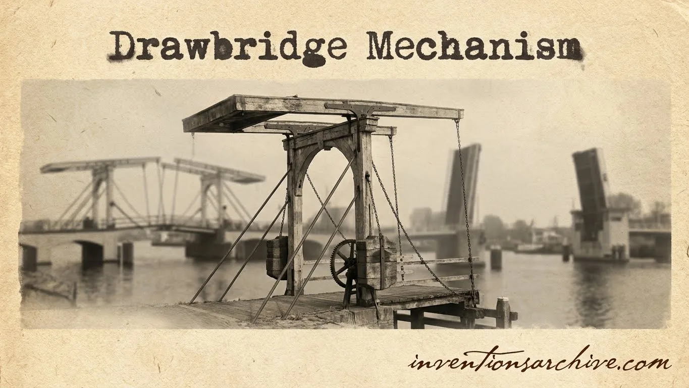
| Invention Name | Drawbridge Mechanism |
| Short Definition | Movable bridge span that lifts to manage crossing access and clearance. |
| Approximate Date / Period | Medieval Europe (likely Normandy) ApproximateDetails |
| Geography | Normandy → wider Europe → global ports and canals |
| Inventor / Source Culture | Anonymous / collective builders |
| Category | Civil engineering; movable structures; access control |
| Importance |
|
| Need / Reason It Emerged | Cross moats/ditches; close quickly; reduce exposure time |
| How It Works (Simple) | Leaf pivots upward; counterweight balances; winch/gears/hydraulics provide torque |
| Material / Technology Basis | Timber + iron hardware → steel + bearings + powered drives |
| First Common Use | Gate crossings; fortified entrances; later waterways |
| Spread Route | Castle regions → towns → canals → modern harbors |
| Derived Developments | Bascule bridges; hydraulic power; automated controls; interlocks |
| Impact Areas | Mobility; navigation clearance; mechanical design; city logistics |
| Debates / Different Views | “First” site and exact dating Contested |
| Predecessors + Successors | Fixed bridges, removable planks → bascule/rolling lift → vertical lift, swing, retractable |
| Key People / Cultures | Norman builders; Victorian engineers; Joseph B. Strauss (20th c.) |
| Types Influenced | Single-leaf; double-leaf; rolling lift; trunnion bascule; draw spans |
A drawbridge mechanism is an elegant piece of motion control: a bridge deck (the leaf) rotates upward so a gap can shift from “closed” to “open” without rebuilding the crossing. In historic settings, the same idea helped manage entry across ditches and moats. In modern settings, it helps keep roads connected while still giving boats and tall vessels the clearance they need.
Table of Contents
What the Drawbridge Mechanism Is
At its simplest, a drawbridge mechanism converts a small, controlled input—human effort, stored energy, or a powered drive—into a large, steady rotation of the bridge leaf. The central idea is balance: by offsetting the leaf’s weight with a counterweight, the system can lift a heavy span with less force and smoother motion.
The word “drawbridge” often brings castles to mind. In engineering terms, it also overlaps with bascule bridges (single-leaf or double-leaf spans that rotate up). The shared concept is the same: a pivoting span that moves through a defined arc while keeping stresses and vibration within safe limits.
Early Evidence and Timeline
The drawbridge idea belongs to a broader family of movable bridges. A widely cited engineering overview notes that the drawbridge (bascule) is the best-known movable form and traces its origin to medieval Europe, likely Normandy, with operation described through a counterweight and winch.Details That description matters because it captures two essentials that still define drawbridge mechanics: balance and controlled torque.
- Medieval era: Timber leaves, iron chains, and internal lifting hardware shaped early drawbridge practice. Mechanisms favored simplicity and serviceability.
- Industrial era: Iron and steel improved stiffness, bearings, and repeatability. Power sources expanded beyond manual effort.
- Modern era: Electric motors and hydraulic systems brought consistent cycles, smoother starts/stops, and more precise position control.
Dating note: Drawbridge development is best understood as a continuum. Early examples varied by region, materials, and site needs, so many “first” claims remain approximate rather than absolute.
Core Parts and Load Paths
A drawbridge mechanism looks dramatic when it opens, yet its real craft shows up when it is closed. That’s when the span behaves like a normal bridge: loads pass through the deck into supports. The mechanism’s parts are designed so the leaf can move freely during lifting, then settle into a stable, repeatable locked geometry when down.
Leaf and Deck
- Leaf: the moving span
- Stiffeners and ribs for shape
- Edge details for smooth seating
Pivot and Bearings
- Pivot (often a trunnion)
- Bearings to reduce friction
- Support framing to carry loads
Balance and Drive
- Counterweight for balance
- Drive: winch, gears, or hydraulics
- Brakes and stops for holding
When the leaf rotates, forces concentrate around the pivot. That’s why drawbridges emphasize bearing quality, controlled speed, and a counterweight tuned to keep the system near neutral balance across most of its travel.
How the Mechanism Works
A drawbridge lift is a sequence of predictable motions. The aim is steady rotation, clean alignment, and controlled stopping—no surprises, no harsh impacts. Good designs treat motion as a managed process, not a sudden event.
- Down position: the leaf rests on supports; alignment features (wedges, guides, or locks) keep the roadway level.
- Initiation: the drive applies torque at the pivot through gears, a winch, or hydraulic cylinders, overcoming static friction.
- Balanced lift: the counterweight offsets the leaf’s mass so required power stays moderate across the arc.
- Open position: the leaf reaches a set angle; brakes and physical stops hold it with stable geometry.
- Closing: motion reverses; the leaf returns to its seat and re-engages alignment so loads pass into the structure as intended.
Why Balance Changes Everything
Without balance, a lifting leaf demands large forces, heavier machinery, and more wear. With balance, the mechanism can focus on precision: smooth starts, clean stops, and repeatable positioning. That is why the counterweight is often the quiet hero of a drawbridge system.
Main Types and Variations
“Drawbridge” is used in two ways: a historic, castle-style lifting deck, and a broader label for movable bridge spans. The mechanisms below share a core idea—creating on-demand clearance—while solving it with different motion paths.
| Type | Motion | Signature Mechanism Feature | Where It Fits Best |
|---|---|---|---|
| Single-Leaf Bascule | One leaf rotates up | Counterweight balances one span | Short spans; simple layouts |
| Double-Leaf Bascule | Two leaves meet at center | Balanced halves reduce required lift height | Wider openings; symmetric channels |
| Rolling Lift (Bascule Variant) | Leaf rolls back as it rises | Rolling path spreads loads; compact machinery | Sites needing lower machinery profile |
| Vertical Lift | Span rises straight up | Hoist + counterweights; towers guide motion | High clearance with minimal swing footprint |
| Swing | Span rotates horizontally | Central pivot; balanced rotating mass | Wide waterways; moderate clearance needs |
| Retractable | Span slides back | Tracks and guided translation | Very constrained vertical space |
In castle-style drawbridges, the typical visual is a single leaf lifting at the gate. In modern infrastructure, “drawbridge” often points to a bascule system—still a leaf, still a pivot, still a balanced lift—just scaled up and automated.
Power, Control, and Safety
Even in a perfectly balanced system, the mechanism needs control. Motion must begin smoothly, hold steady speed, then stop accurately. That is why drawbridges rely on a tight relationship between the drive, the braking system, and position feedback (from mechanical limits to modern sensors).
Counterweights as a Safety Tool
A practical inspection guide for bascule bridges explains two core reasons for counterweights: they reduce the size of required mechanical systems and they add an extra margin of safety if a control or mechanical problem leads to runaway motion.Details In plain terms, balance makes the system less demanding and more forgiving.
- Drive options: manual winches (historic), electric motors (common), hydraulic cylinders (high torque and smooth control).
- Holding options: brakes, mechanical locks, and physical stops to keep the leaf steady at set positions.
- Interlocks: systems that coordinate road barriers, signals, and bridge motion so the sequence stays orderly.
- Alignment hardware: guides and seating surfaces that return the roadway to the same level position each cycle.
Materials and Technology Shifts
Drawbridges started with timber leaves and iron fittings because those materials matched local craft. As spans grew and cycles increased, materials and components changed. Steel, improved bearings, and refined gearing gave drawbridges a more predictable service life.
Historic Hardware
- Chains and links
- Wooden beams and decking
- Simple winches and drums
- Iron straps and pins
Modern Components
- Counterweight boxes (often concrete/steel)
- High-grade bearings
- Gear trains and racks
- Hydraulic power units
What stayed constant is the underlying physics: manage moments around the pivot, keep friction low, and maintain a stable seating condition for the “down” position. The best systems feel quiet in operation because loads and motion are balanced, not forced.
Modern Examples and Descendants
Modern bascule bridges often look like a giant drawbridge, and the mechanism is familiar: a leaf rotates around an off-center pivot while balance reduces energy demand. An accessible example is Tower Bridge, which describes its bascules as evenly balanced around an off-centre pivot and notes that the opening work is handled by eight large cogs (about 1m in diameter), with power shifting from steam to electricity and later to an electro-hydraulic system installed in the 1970s.Details
A 20th-Century Engineering Thread
As city waterways demanded reliable openings, movable-span design became a specialized discipline. Archival collections help map that shift. A Stanford archival guide documents Joseph Strauss bridge plans from 1905–1935 and lists multiple movable-span forms, including bascule and vertical draw spans, reflecting how drawbridge mechanics matured into a family of standardized draw-span solutions.Details
Today, the drawbridge mechanism lives on wherever a crossing must stay connected yet still “make room” at certain times. The vocabulary may change—bascule, lift, swing—but the heart of it is still controlled motion, balanced loads, and dependable return to a level roadway.
FAQ
What is a drawbridge mechanism?
A drawbridge mechanism is a system that lifts a bridge leaf through a controlled arc or lift path. The signature features are repeatable motion and stable seating in the down position, with balance often supported by a counterweight.
Is a drawbridge the same as a bascule bridge?
Many people use “drawbridge” for any movable span that rises. In engineering terms, a bascule is a pivoting leaf system. Historic drawbridges fit that family closely, even when materials and drives differ.
Why do drawbridges use counterweights?
A counterweight offsets leaf weight so the drive does not “fight gravity” at full force. The result is lower energy demand, smoother motion, and a more controlled stop—an important part of reliable operation.
What keeps the roadway level when the bridge is down?
Drawbridges rely on alignment features: seating surfaces, guides, and locking elements that bring the leaf back into the same geometry each time. That repeatability protects comfort, load transfer, and long-term wear.
Why are hydraulics common in modern drawbridge systems?
Hydraulics can deliver high torque with fine speed control. That makes it easier to manage heavy leaves, handle smooth starts, and achieve precise stopping—especially when cycle consistency is important.
Do drawbridge mechanisms still matter today?
Yes. The same underlying idea—movable clearance without losing the crossing—still supports busy waterways and urban routes. The outward form changes, yet the mechanism’s logic remains timeless.