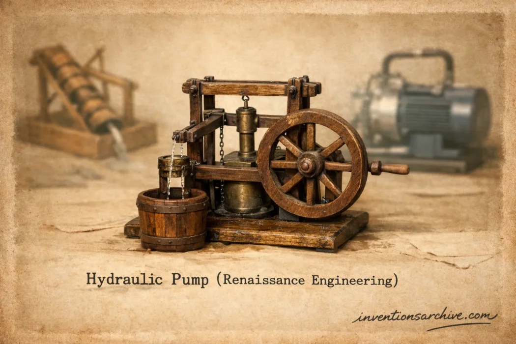
| Invention Name | Hydraulic Pump (Renaissance Engineering) |
| Short Definition | Machine that raises or moves water by converting mechanical input into fluid pressure and flow |
| Approximate Date / Period | 15th–16th centuries (European Renaissance) (Approximate) |
| Geography | Italian city-states, Central Europe mining regions, Mediterranean ports |
| Inventor / Source Culture | Anonymous / collective; refined by Renaissance engineers and workshops |
| Category | Water management, mining, civil engineering, safety equipment |
| Importance | Mine drainage; urban water supply; fountains and workshops; early industrial scaling |
| Need / Reason For Emergence | Deeper mines, denser cities, reliable water delivery beyond gravity channels |
| How It Works | One-way valves + piston/rotary lift create directed flow; pressure overcomes height and friction |
| Material / Technology Basis | Wood and iron frames; bronze/iron cylinders; leather seals; flap or poppet valves |
| First Common Uses | Mine dewatering; ship bilges; town waterworks; fire-fighting hand pumps |
| Spread Route | Workshop practice + illustrated treatises; mining networks; port cities |
| Derived Developments | Better valves and seals; multi-cylinder pumping; powered pump trains; standardized components |
| Impact Areas | Engineering, urban infrastructure, crafts, mining productivity, public safety |
| Predecessors + Successors | Predecessors: water-lifting screws, bucket chains, early piston ideas; Successors: industrial piston pumps, rotary pumps, modern hydraulic power units |
| Key People / Traditions | Renaissance engineering notebooks; mining authors and practitioners; city waterworks builders |
| Noted Variations Influenced | Lift (suction) pumps; force pumps; double-acting pumps; chain-and-bucket pumps; screw-driven lifters |
| Debates / Different Views | “First inventor” unclear; many designs evolved from older water-lifting traditions |
Hydraulic pumps in the Renaissance were not a single gadget with a single inventor. They were a family of water-moving machines that grew sharper and more dependable as cities expanded and mines went deeper. What made them feel “new” was the way workshops combined valves, pistons, seals, and power sources into systems that could keep working day after day—often under pressure that gravity channels alone could not handle. Renaissance engineering turned water lifting into repeatable practice.
Table Of Contents
Choose a section and go straight to the details. Each part explains the mechanics, the use cases, and the design logic behind Renaissance hydraulic pumping.
What Hydraulic Pumps Are
A hydraulic pump is a device that spends energy to move fluid. In Renaissance settings, that usually meant raising water from a low place to a higher one, or pushing it through pipes where gravity alone could not keep a steady flow. The defining idea is simple: create a controlled pressure difference, then let water follow it. That pressure can come from a hand lever, a treadle, animal power, or a wheel driven by water itself. Pressure-driven flow was the point, and it fit perfectly with the growing appetite for reliable water control.
Britannica describes a pump as a device that raises, transports, or compresses fluids, and notes that mining needs drove major development of the suction (piston) pump and the higher-lift force pump, including a suction-lift limit of about 10 metres. (Details-1)
Renaissance Challenges That Pumps Solved
Renaissance pumping mattered because it answered problems that were already pressing and expensive. Water had to be where people worked and lived, not only where channels could reach. Pumps supplied that flexibility. The machines were also “scalable”: add cylinders, improve seals, change the drive, and the same core concept served new tasks. In that sense, hydraulic pumping was a practical platform, not a one-off trick. Urban growth and deeper extraction made the demand constant.
- Mine drainage: water had to be lifted out continuously to keep shafts usable.
- City waterworks: pushing water to tanks, fountains, and workshops where elevation and distance varied.
- Fire safety: hand-driven pumps supported early organized response in dense neighborhoods.
- Ports and ships: bilge removal relied on dependable lifting, even with limited space.
- Craft production: tanning, dyeing, milling, and metalworking benefited from steady water movement.
Why pumps beat “just build a channel”: channels need slope and space; pumps work with tighter geometry. A workshop could be uphill, a mine could be deep, and a city could be crowded. Pressure made water routes flexible. That flexibility is the quiet reason pumps became essential.
How A Piston Pump Works
The Renaissance workhorse was the piston-and-valve idea. A cylinder fills and empties in a controlled cycle. The critical detail is the valve arrangement: water is allowed to enter on one phase and forced to exit on another, always in one direction. Without that one-way logic, the motion would only slosh. With it, the motion becomes flow. The result is directed pumping built from simple moving parts plus tight sealing.
Suction Pump
- Lift logic: the rising piston creates lower pressure in the cylinder.
- Atmospheric pressure pushes water up into the cylinder.
- Limit: practical lift is capped because air pressure can only support a finite water column.
Force Pump
- Push logic: the piston compresses water and drives it out through a discharge valve.
- Valves prevent backflow when the piston resets.
- Advantage: lift depends on applied force and construction strength, not atmospheric lift alone.
Even when the parts were made of wood and iron, builders treated the interface between piston and cylinder as the heart of the machine. A small leak turns pressure into waste. That is why seals, valve seats, and smooth bores mattered so much. It is also why these pumps were a workshop achievement: they rewarded careful fitting more than flashy geometry. Seal quality shaped performance as much as clever mechanisms. Precision was practical, not decorative.
Key Pump Types Seen In Renaissance Sources
Renaissance engineering references point to several families of water-lifting and pumping. Some are piston-based, others are continuous-lift devices. Grouping them by motion makes the landscape clearer. The main difference is whether the machine moves a fixed volume per cycle (positive displacement) or lifts water continuously by carrying it upward (continuous lift). Both appear in Renaissance thinking and practice.
| Pump Family | Core Motion | Strength | Typical Renaissance Fit |
|---|---|---|---|
| Suction (Lift) Pump | Piston creates lower pressure to draw water in | Simple, good for shallow lifts | Wells, workshops, ship bilges |
| Force Pump | Piston pushes water through a discharge valve | Higher lift, adaptable to pipes | Mines, town delivery, fire pumps |
| Double-Acting Piston Pump | Two-phase discharge reduces “pulsing” | Smoother flow | Longer runs, steadier supply |
| Chain-And-Bucket Pump | Continuous lift with moving chain and cups | Robust for large volumes | Drainage, irrigation, lifting from pits |
| Archimedes Screw | Rotary spiral carries water upward | Steady with rotation | Low-to-moderate lift, bulk transfer |
Why These Types Coexisted
A mine might need pressure to push water up and out. A canal project might prefer a steady rotary lift. A city fountain could benefit from a pump that tolerates long pipes and changing demand. The Renaissance did not “pick one.” It assembled a toolkit. Context decided the machine.
Materials and Power In Workshops and Mines
Renaissance pumps were engineered around what builders could reliably make and maintain. Materials shaped design choices. Wood was easy to work and repair. Iron handled stress. Bronze offered smoother surfaces and resisted corrosion in many water settings. The sealing problem was often solved with leather, fiber packing, and careful fitting. A pump that looked “simple” could still be a demanding craft object. Workmanship mattered because pressure finds gaps. Durability was earned.
- Frames and linkages: timber beams, iron straps, pegged joints, replaceable pins.
- Cylinders: bored wood with liners, or cast/forged metal for longer life.
- Valves: flap valves, simple seats, and guided plugs to keep flow one-way.
- Seals: leather cups, packing, greased fibers to reduce leakage and wear.
- Power inputs: hand levers, treadles, animal drives, and waterwheels for continuous work.
Hand And Treadle Drives
Human-powered pumps favored short bursts, direct control, and quick repair. The rhythm could be uneven, so builders used air chambers or multiple cylinders where a steadier output mattered. Simple leverage met urgent needs in towns and ships.
Waterwheel Trains
When a stream could supply rotation, the pump could run longer and lift more. The challenge was converting rotation into a pumping stroke and keeping timing consistent. Rotary-to-reciprocating mechanisms and gearing made that possible. Continuous power supported continuous drainage.
From Sketches To Practice
Renaissance hydraulic pump knowledge traveled through hands-on craft and through drawings that preserved mechanisms in a shareable form. Some drawings explored ambitious systems; others captured proven workshop solutions. That mix is useful today because it reveals what engineers thought was difficult: priming, leakage, valve timing, and drive conversion. Engineering sketches show problem awareness, not only imagination. Details were the story.
Museo Galileo’s presentation of a Codex Atlanticus sheet describes Leonardo’s study of self-powered water-lifting machines, including an integrated priming system with a chain pump, and dates the sheet to approximately 1480. (Details-2)
The National Coal Mining Museum notes that De Re Metallica was the most important mining text for nearly two centuries after its publication, and that it uses woodcut drawings to show tools and machinery—exactly the kind of visual evidence that preserves pumping systems and their context. (Details-3)
Royal Collection Trust records Leonardo’s diagram “A water-wheel geared to an Archimedes screw,” a compact example of Renaissance thinking about coupling a power source to a water-lifting device. That coupling is a recurring pattern in pumping history. (Details-4)
What Drawings Reveal About Real Constraints
- Priming: getting the first water into the mechanism so it can keep going.
- Backflow control: valves and seats that do not leak under cycling.
- Drive conversion: turning wheel rotation into a repeatable pumping stroke.
- Maintenance: parts designed to be replaced, not only admired.
Design Limits and Reliability
Renaissance pumps were limited by physics and by materials. The physics side is easy to state: a suction pump cannot lift water beyond the height atmospheric pressure can support. The materials side is more subtle: higher pressure amplifies stress and leakage, so a pump meant for deeper work needed stronger cylinders, tighter valves, and a sturdier drive. The two limits meet in one sentence: shallow lifts favor suction pumps; deeper lifts favor force pumps. Lift height is never “free.” It is paid for with force and construction quality.
- Leakage: small gaps cut effective pressure and reduce lift.
- Valve wear: a tired seat means backflow, lower output, and harder priming.
- Pulsing flow: single-cylinder pumps can surge; multi-cylinder layouts smooth delivery.
- Contaminants: grit damages seals and valves faster than most designs can tolerate.
- Friction losses: longer pipes and tight bends demand more pressure for the same output.
Reliability improved when builders treated pumping as a system: intake, cylinder, valves, discharge, and power train. That systems view is one reason Renaissance pumping feels modern. It moved past “a clever part” and toward “a dependable arrangement.” Systems thinking was present in the hardware, even when the language was different. Consistency mattered. Downtime was expensive.
Frequently Asked Questions
Clear answers to common questions about Renaissance hydraulic pumps and the machines closely associated with them. This section is designed to be easy to scan.
Were Renaissance hydraulic pumps “hydraulics” in the modern sense?
They focused on moving water and creating usable pressure, which is the core idea behind modern hydraulics. Modern hydraulic systems often use oil and closed circuits to transmit power. Renaissance machines were usually open-water systems meant for lifting, drainage, or delivery.
Why does a suction pump have a height limit?
A suction pump relies on atmospheric pressure to push water upward into a lower-pressure space. Once the water column is too tall, air pressure cannot support it. That is why deeper drainage pushes designs toward force pumps that actively pressurize the water.
What made force pumps better for mines?
Force pumps push water out under pressure through a discharge path, so they can lift from deeper levels when built strongly enough. They also pair well with piping, letting water be guided to a safe outlet rather than spilling near the work area.
How are chain pumps different from piston pumps?
Chain pumps lift water continuously using moving cups or buckets on a loop, while piston pumps move water in discrete cycles using a cylinder and valves. Chain pumps can be strong for bulk movement; piston pumps can be compact and can generate higher pressure for piping.
Did Renaissance engineers build pumps exactly as drawn?
Drawings include both practical designs and exploratory ones. Even when a drawing is not a direct blueprint, it can still be valuable evidence: it shows what problems the engineer considered important and which mechanisms were seen as plausible.
What parts decide pump performance the most?
Seals, valves, and the fit of moving parts often decide more than the overall layout. A strong drive cannot compensate for major leakage. A well-seated valve can turn a simple cylinder into a dependable pump.