
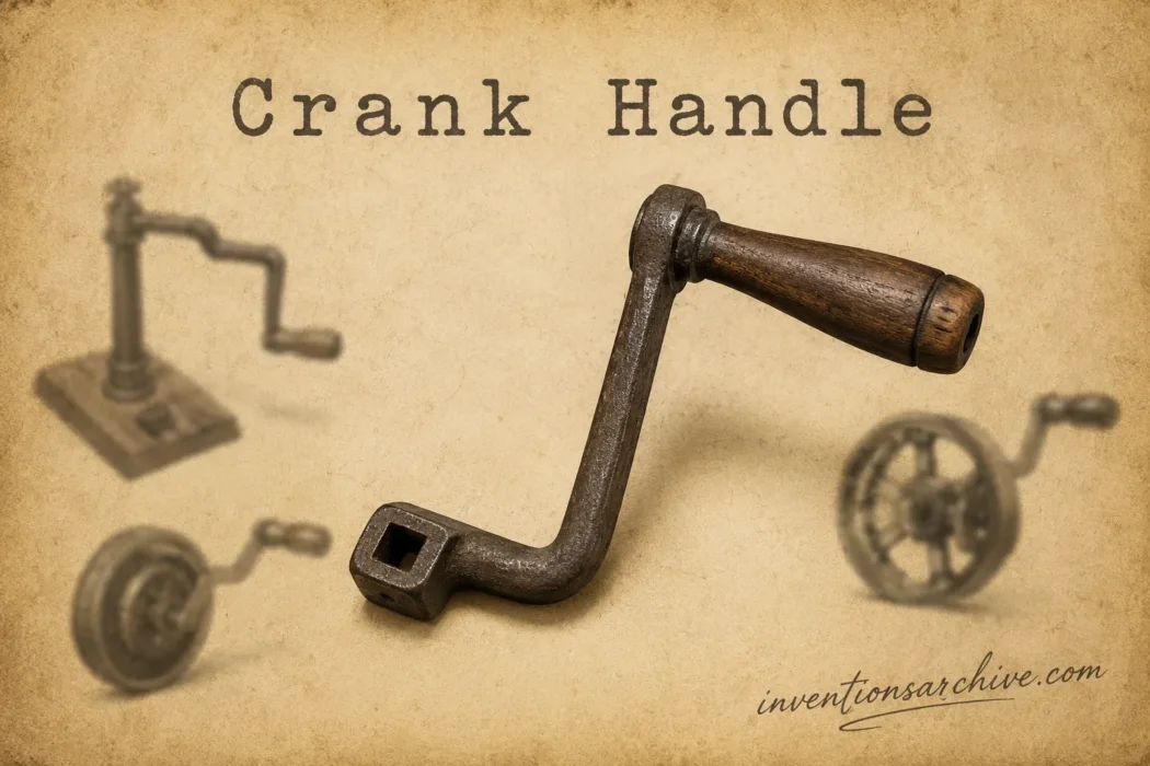
| Invention Name | Crank Handle |
|---|---|
| Short Definition | An offset arm with a hand grip that turns a shaft around its axis. |
| Approximate Date or Period | Attribution varies Hand-crank forms appeared in antiquity; securely documented crank systems survive from later ancient contexts. |
| Geography | Multiple regions, with early evidence from the Mediterranean world, Roman Asia, and ancient China. |
| Inventor or Source Culture | No single inventor can be confirmed; different cultures developed related rotary devices and crank mechanisms. |
| Category | Mechanical control; hand-powered rotary motion. |
| Importance | Made it practical to apply repeated human force to a shaft with leverage, speed control, and continuous rotation. |
| Evidence Status | Based on surviving evidence Early dates depend on whether an offset grip, a true crank, or a crank-and-connecting-rod machine is being discussed. |
| Main Problem Solved | Converted repeated hand movement into controlled rotary motion without requiring the hand to be repositioned after each partial turn. |
| How It Works | Force applied at an offset grip creates torque around the shaft; the rotating grip lets the hand follow a circular path with less rubbing. |
| Development Path | Direct turning and rotary querns → offset hand grips → crank-and-rod mechanisms → geared hand machines → folding, retractable, and disengaging controls. |
| Modern Descendants | Winches, window operators, machine handwheels, manual overrides, reel drives, jacks, generators, and adjustment mechanisms. |
A crank handle places the hand away from the center of a shaft. As the user moves the grip around that center, the arm turns the shaft through a complete circle. The arrangement is mechanically simple, yet it solves several problems at once: it adds leverage, gives the hand a repeatable path, permits steady speed control, and can feed motion into gears, drums, screws, pumps, or linkages.
The word crank can describe several related parts. A hand crank is the manually operated arm and grip. A crankshaft contains one or more offset journals within a rotating shaft. A crank-and-connecting-rod mechanism links rotation to reciprocating motion. These forms share the use of an offset from the axis, but they do not have the same history or purpose.
Why Direct Turning Was Not Enough
A shaft can be turned by gripping its end, pushing a peg, pulling a cord, or pressing against the rim of a wheel. Each method works under limited conditions. Directly gripping a narrow shaft produces little leverage. Pushing a fixed bar through part of a turn requires the hand to release and take a new position. Pulling a cord creates motion in one direction and then demands a return stroke or rewinding.
The crank handle gave the hand a continuous circular route. Its offset arm increased the distance between the applied force and the axis, while the grip provided a defined place to hold. The user could keep turning without repeatedly stopping to reset the tool.
| Earlier Method or Limitation | Change Introduced by the Crank Handle |
|---|---|
| Gripping a shaft close to its axis produced little turning effect. | The offset arm increased the lever distance and therefore the available torque. |
| A fixed bar often allowed only a partial turn before the hand had to move. | The grip could travel repeatedly around the axis through full rotations. |
| Pull cords and treadles produced alternating strokes. | A crank could deliver continuous rotary motion or connect to a rod to create controlled reciprocation. |
| Turning a rim required access to a large wheel. | A compact handle could operate a shaft, gear train, drum, or screw in a smaller control area. |
How an Offset Handle Produces Torque
The center shaft is the axis of rotation. The crank arm extends away from that axis, and the grip sits at or near the outer end. The distance from the shaft center to the point where the hand applies force is the crank radius, also called the throw in some mechanisms.
The turning effect is torque. For a force applied perpendicular to the arm, the relationship is:
Torque = Force × Crank Radius
A hand force of 100 newtons applied perpendicular to a crank radius of 0.20 metre produces a theoretical torque of 20 newton-metres. The same force on a 0.10-metre radius produces 10 newton-metres. When the force is not perpendicular, only the perpendicular part contributes fully to rotation. OpenStax expresses the general relation as τ = rF sin θ, where the angle between the arm and the force changes the result.[a]
This explains why a longer crank can make a heavy mechanism easier to start. It also explains why length cannot be increased without limit. A longer arm needs a wider clear area, makes the hand travel farther during each revolution, and may become awkward at higher speed.
The Main Parts of a Hand Crank
- Shaft connection: the socket, keyed joint, square fitting, spline, pin, or fastener that transfers rotation into the machine.
- Hub: the section surrounding or joining the shaft connection.
- Crank arm: the offset member that establishes the lever distance.
- Grip or knob: the part held by the user.
- Grip spindle: the small axis around which a free-running grip rotates.
- Optional joint or clutch: a folding, retracting, ratcheting, removable, or disengaging feature used in later designs.
Why the Grip Rotates While the Arm Circles the Shaft
A rigid arm and a freely rotating grip perform different movements. The arm revolves around the machine shaft. The grip travels with the arm but can also turn around its own smaller spindle.
Without that second rotation, the surface of a fixed knob would rub across the palm during every revolution. The hand would have to loosen, slide, or twist at the wrist. A free-running wooden, metal, or polymer sleeve lets the grip roll beneath the hand instead. Bushings or bearings can reduce resistance further in frequently operated mechanisms.
This feature separates a practical continuous crank from a simple peg used for an occasional quarter-turn. The shape and diameter of the grip also matter. A narrow knob concentrates pressure, while a larger cylindrical handle spreads the load across more of the hand. Designers must balance grip comfort against available space, required speed, gloves, and the surrounding machine body.
From Offset Grips to Crank-Driven Machines
The history is best understood as a set of documented stages, not a single moment of invention. A hand grip used to rotate a quern solves a different task from a crank wheel driving saw frames, even though both place force away from an axis.
| Stage | Form | What Changed |
|---|---|---|
| Direct Rotary Work | Hand-turned stones, drums, reels, and shafts | Human force produced rotation, but leverage and continuous grip varied with the object. |
| Offset Hand Grip | Peg or handle placed away from the center | The hand gained a circular path and a larger lever distance. |
| Roman Crank-and-Rod Evidence | Hierapolis water-powered twin stone saw, late third century | Crank wheels and connecting rods converted wheel rotation into the back-and-forth movement required by saw frames. |
| Chinese Mechanical Applications | Agricultural, textile, and blowing machinery described in literature and surviving evidence | The crank-and-rod principle appeared in several work processes rather than one isolated machine. |
| Geared Hand Machines | Workshop tools, reels, presses, sewing machines, pumps, and domestic equipment | The handle became an input control for gear trains and repeated mechanical cycles. |
| Safer Stored Forms | Folding, retractable, removable, and automatically disengaging handles | Later designs reduced unwanted projection and separated the manual control from powered shaft rotation. |
The Hierapolis Distinction
The Hierapolis relief does not show a person turning a small hand crank. It shows a powered machine. Water turns a wheel, a gear train transfers that rotation, and crank wheels with connecting rods move two saw frames back and forth. Its value lies in confirming a mature motion-conversion system in the late Roman period.
The same distinction prevents an exaggerated claim. Evidence that a culture knew a crank-and-rod system does not identify the inventor of every hand-operated crank. It proves knowledge and application within a dated setting; it does not establish the first use of every related form.
Regional Development in Ancient China
Ancient Chinese crank-and-connecting-rod applications covered more than one trade. The reviewed evidence includes agricultural processing, textile machinery, and blowing engines. That range matters because it shows how the mechanism could migrate between tasks that required rotation, reciprocation, or both.
The records are not a complete year-by-year chain. Written descriptions may postdate practical use, and many working parts were made from materials that rarely survive. The safest historical conclusion is that crank mechanisms developed through repeated adaptation across regions and occupations.
When Rotation Must Become Back-and-Forth Motion
A crank handle can turn a shaft directly, but adding a connecting rod changes the output. One end of the rod follows the circular crank pin. The other end is constrained by a piston, slider, saw frame, pump rod, or similar guide. The result is reciprocating movement.
This conversion allowed rotary power to operate pumps, saws, and later engines and production machinery. The direction can also be reversed: a piston moving back and forth can drive a crankshaft in rotation. The hand crank belongs to the same geometric family, though its usual role is to provide the rotary input rather than receive reciprocating power.
The Dead-Center Problem
A crank-and-rod mechanism does not transmit force equally at every angle. When the crank and connecting rod approach a straight line, the rod has little sideways leverage on the crank. At exact alignment, the mechanism reaches a dead-center position.
A person operating a hand crank can often carry the handle through this point by momentum or by changing the direction of hand pressure. Machines use flywheels, multiple cranks set at different angles, counterweights, or several cylinders to keep motion moving through positions where one crank has poor leverage.
Related articles: Bow Drill Tool [Ancient Inventions Series], Gramophone [Industrial Age Inventions Series]
Dead center is not a defect in one badly made handle. It follows from the geometry of converting circular and linear motion. Direct rotary devices, such as a reel or grinder driven straight from the handle, do not face the same alignment problem because no connecting rod is present.
How Crank Handles Entered Everyday Machines
Mills, Grinders, and Food Equipment
A crank allowed a person to rotate a millstone, grinding wheel, mixer, or cutting drum at a chosen pace. Gearing could trade speed for torque. A small gear driven by the handle might turn a larger gear slowly with greater output torque, while the opposite arrangement could produce faster shaft rotation for light work.
Reels, Winders, and Winches
Reels require steady rotation and control over tension. A crank gave the operator direct feedback as rope, wire, thread, film, hose, or cable accumulated on a drum. Winches added gearing, ratchets, and brakes so the operator could move heavier loads while limiting reverse movement.
Workshop and Adjustment Tools
Hand drills, braces, vises, jacks, lead screws, machine slides, and positioning controls used the same principle in different ways. Some needed many quick turns. Others needed slow, forceful adjustment. The selected crank radius, gear ratio, and grip shape reflected the job rather than a single standard design.
Sewing and Repetitive Production
Hand-operated sewing machines show how a crank became the entrance to a sequence of linked motions. The Smithsonian’s 1843 Benjamin W. Bean patent model used a crank handle to move gearing that produced a running stitch. The handle did not act on the needle alone; it coordinated a cycle through the machine’s internal parts.[d]
Printing presses, small pumps, cash registers, and workshop machines followed the same broad pattern. Human rotation entered at the handle, then cams, gears, shafts, and linkages distributed it to the working components.
Starting Cranks and the Shift to Electric Starting
Early gasoline automobiles commonly used a removable starting crank connected to the engine’s crankshaft. Turning the handle rotated the engine through the intake and compression cycle until combustion began. Once the engine started, the handle had to stop driving with the shaft.
Starting cranks did not disappear from every engine at once. They remained on some vehicles, stationary engines, and emergency systems. Their history exposed a broader design issue: a manual handle is safe only when the powered shaft cannot unexpectedly drive it at dangerous speed.
Fixed, Folding, Retractable, and Disengaging Designs
The early crank’s visible simplicity created later problems. A permanently projecting handle could catch clothing, interfere with nearby objects, or strike someone if the connected shaft began to rotate. Designers responded by changing how the handle was stored and how it engaged the machine.
| Design Form | Mechanical Purpose | Main Limitation |
|---|---|---|
| Fixed crank | Always available for frequent manual operation. | Remains as a projection and may rotate with the shaft. |
| Folding crank | Pivots toward the machine or handwheel when not in use. | The hinge and locking feature add wear points. |
| Retractable crank | Moves the arm or knob into a recess to reduce obstruction. | Needs additional springs, guides, or retaining parts. |
| Removable crank | Prevents casual operation and leaves no permanent projection. | The separate handle can be misplaced and may not be ready during an emergency. |
| Ratcheting crank | Turns a shaft through repeated short strokes where a full circular sweep is blocked. | Produces interrupted input and adds pawl-and-tooth wear. |
| Disengaging handwheel or crank | Separates the manual control when a motor drives the shaft. | Requires a dependable clutch, cam, lockout, or speed-sensitive mechanism. |
A 1970 United States patent for a retractable crank described a spring-biased arm stored within a handwheel, with the knob held in a niche when not in use. The stated goals included dependable operation and reducing the chance of injury from a projecting knob in vehicle window and roof controls.[f]
A later handwheel patent addressed another danger: a manual wheel remaining connected when a powered shaft rotates at high speed. Its mechanism automatically disengaged the handwheel above a set shaft speed and prevented the user from re-engaging it under that condition. This approach treats separation from powered motion as part of the control design rather than relying only on operator caution.[g]
Materials Changed More Than the Basic Geometry
The offset-arm principle remained recognizable while construction changed. Early handles could use wood for the grip and arm because it was easy to shape and comfortable in the hand. Iron and steel allowed thinner arms, stronger shaft joints, and higher working loads. Cast metals made complex hubs and curved forms easier to reproduce.
Modern grips often use molded polymers over a metal spindle. The polymer can provide a larger hand surface, resist moisture, and insulate the hand from a cold or hot metal arm. Bushings may use bronze or engineered plastics, while rolling bearings suit handles expected to turn frequently at higher speed.
Material choice cannot be separated from failure mode. A wooden grip may split or swell. A metal arm may bend, corrode, or fatigue near a sharp change in section. A square socket or spline may wear until the handle moves before the shaft does. Folding joints can loosen, and a seized grip can force the user’s palm to slide instead of allowing the knob to roll.
What Determines Crank Length and Shape
The correct crank radius depends on the required torque, the force a person can apply comfortably, and the available sweep around the machine. A longer arm reduces the force needed for a given torque. It also increases the distance travelled by the hand during each revolution.
One complete turn moves the grip through a circular distance of 2πr. A 0.10-metre radius gives a hand path of about 0.63 metre per revolution. A 0.20-metre radius doubles that path to about 1.26 metres. The longer handle may feel easier under load, yet it demands more arm movement and more clearance.
Speed changes the choice. A short crank suits light mechanisms that must turn rapidly. A long crank suits slow movement against resistance. Bent arms can clear nearby housings. Counterbalanced handles reduce uneven feel at speed. Two-hand arrangements divide effort, while a ratchet permits operation where a full circle is impossible.
Why the Crank Handle Remains Useful
Electric motors replaced hand cranks in many repetitive and high-power tasks, but manual rotary controls still serve roles that motors do not always improve. A crank can operate without electricity, give immediate tactile feedback, hold a slow adjustment, and remain usable after long periods of inactivity.
Machine tools retain handwheels and cranks for positioning. Windows and vents use them to multiply force through gears. Winches and reels use them where direct control matters. Valves and powered mechanisms may include manual overrides so a shaft can still be moved during maintenance or loss of power.
The modern form is often less exposed than its earlier counterpart. Folding arms, recessed knobs, removable handles, clutches, and automatic disengagement preserve the direct relationship between hand force and shaft rotation while addressing the hazards created when a simple projecting handle is attached to a powered machine.
Sources and Verification
- [a] 10.6 Torque – University Physics Volume 1 — Used to verify the relationship among torque, force, lever arm, and application angle. (Reliable because OpenStax publishes reviewed university-level physics material through Rice University.)
- [b] A stone relief of a water-powered stone saw at Hierapolis, Phrygia — Used to verify the late third-century relief, its crank wheels, connecting rods, gear train, and the limits of attributing the mechanism to Ammianos. (Reliable because it is a scholarly archaeological and technology-history publication hosted by OpenEdition Books.)
- [c] Crank-Connecting Rod Mechanism: Its Applications in Ancient China and Its Origin — Used to verify documented applications in agriculture, textile work, and blowing engines in ancient China. (Reliable because it is a scholarly chapter published by Springer in a history-of-mechanisms volume.)
- [d] 1843 – Benjamin W. Bean’s Patent Model of a Sewing Machine — Used to verify the crank-handle operation and gearing of the 1843 sewing-machine patent model. (Reliable because it is a direct object record from the Smithsonian National Museum of American History.)
- [e] Driving with Disabilities: Early Pioneers — Used to verify Charles F. Kettering’s 1911 electric automobile starter and its place in replacing manual engine starting. (Reliable because it is a curated Smithsonian National Museum of American History exhibition page.)
- [f] US3517571A – Retractable crank for the manual actuation of an opening and closing device — Used to verify the spring-biased retractable arm, recessed knob, intended vehicle applications, and stated injury concern. (Reliable because the page reproduces the published United States patent text, drawings, claims, and bibliographic record.)
- [g] US4194412A – Handwheel disengage mechanism — Used to verify automatic separation of a manual handwheel from a powered shaft above a predetermined speed. (Reliable because the page reproduces the published United States patent description, claims, and bibliographic record.)