
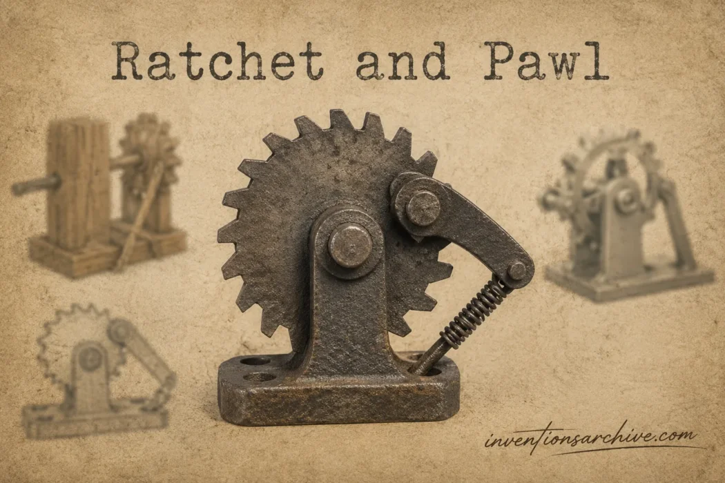
| Invention Name | Ratchet and Pawl |
|---|---|
| Short Definition | A toothed mechanism that permits stepwise movement in one direction while resisting movement in the other. |
| Approximate Date or Period | Exact origin uncertain; documented in Renaissance engineering drawings and widely classified by the nineteenth century. |
| Geography | Documented in European manuscript and industrial engineering traditions; later adopted worldwide. |
| Inventor or Source Culture | Attribution varies; no single inventor can be confirmed. |
| Category | Mechanical motion control; intermittent-motion and one-way locking mechanism. |
| Importance | Converts repeated strokes into retained progress and prevents unwanted reverse motion without continuous input. |
| Evidence Status | Based on surviving evidence; drawings, educational models, patent models, machines, and later patents survive. |
| Main Problem Solved | Loss of position or load when an operating handle returned, stopped, or changed direction. |
| How It Works | A pawl rides over sloped tooth faces in the allowed direction and bears against locking faces during reverse motion. |
| Material or Technical Basis | Asymmetric teeth, a pivoted or flexible pawl, controlled engagement, and a supporting structure that carries the reaction load. |
| Early Use Context | Hoisting, winding, clocks, intermittent drives, and mechanisms that had to retain each completed step. |
| Development Path | Documented locking forms → classified industrial mechanisms → specialized tools and machines → multi-pawl and compliant designs. |
| Modern Descendants | Ratchet wrenches, lifting devices, tensioners, mechanical counters, freewheels, indexed joints, and printed compliant mechanisms. |
The Motion Problem Behind the Mechanism
Many machines are operated by a handle that swings through a limited arc. The useful stroke may turn a shaft, lift a load, wind a spring, or advance a counter. The return stroke creates a problem: the handle must come back without undoing the movement already gained.
A second problem appears when the operator stops. Gravity, spring tension, an external load, or stored torque may try to reverse the shaft. A plain lever and wheel do not distinguish between the intended direction and the unwanted one. The ratchet and pawl adds that distinction through shape and contact.
| Without Directional Locking | With a Ratchet and Pawl |
|---|---|
| A returning handle can turn the driven part backward. | The handle can reset while the driven part retains its position. |
| A suspended or tensioned load can reverse the mechanism when input stops. | A holding pawl can oppose reverse rotation at the next engaged tooth. |
| Short strokes do not accumulate unless another device retains each movement. | Repeated strokes can produce indexed, step-by-step progress. |
| Position must be held by continuous force, friction, or a separate stop. | Positive tooth engagement can retain position without continuous operating force. |
This retained progress is sometimes described as a form of mechanical memory. The mechanism does not record information in the electronic sense. It preserves the result of the previous stroke by refusing the reverse movement that would erase it.
How the Ratchet Cycle Works
The familiar circular version contains a ratchet wheel, a pawl, a pivot or flexible support, and some means of maintaining contact. The teeth are asymmetric. One face allows the pawl to climb and pass; the other presents a surface against which the pawl can lock.
| Part | Mechanical Function | What It Experiences |
|---|---|---|
| Ratchet Wheel | Provides a sequence of directional teeth around a shaft or moving member. | Tooth contact, torque, impact, and surface wear. |
| Pawl | Passes over teeth in one direction and blocks a tooth face in the other. | Tip contact, bending, repeated impact, and pivot reaction. |
| Spring or Gravity Bias | Keeps the pawl near the tooth path so it can re-engage. | Repeated deflection; normally it is not intended to carry the main locked load. |
| Pivot or Flexible Joint | Allows the pawl to rise, fall, engage, and release. | Bearing pressure, friction, and alignment error. |
| Housing or Frame | Maintains the geometry between the wheel, pawl, and shaft. | The reaction force transmitted from the engaged pawl. |
1. Engagement
The pawl rests in a tooth space or against a locking face. A spring, gravity, or the pawl’s own elastic shape keeps it in the engagement path.
2. Allowed Movement
As the wheel turns in the permitted direction, the rising tooth profile pushes the pawl away. The pawl slides or rolls across the tooth tip while the wheel continues to move.
3. Reset
After the tooth passes, the pawl drops into the next space. The clicking sound of many ratchets comes from this repeated lift, release, and impact.
4. Reverse Locking
If the wheel begins to turn backward, the locking face presses against the pawl. The load then travels from the wheel tooth through the pawl and its support into the surrounding frame. Reverse movement stops after the available clearance has been taken up.
The word ratchet is sometimes used for the entire assembly, but the wheel and pawl perform different tasks. The wheel supplies the directional tooth sequence. The pawl interprets that geometry by engaging, passing, or locking.
Driving Pawls, Holding Pawls, and the Load Path
Not every pawl in a ratchet mechanism has the same job. A driving pawl is connected to a lever or other input and advances the ratchet during the useful stroke. A holding pawl remains connected to the frame and prevents the wheel from returning while the driving pawl resets.
Cornell’s crown-wheel lifting model demonstrates this division with two pawls and a lever-driven lifting arrangement. One pawl moves with the lever and advances the wheel; the other preserves the gained position while the lever returns.[c]
The same logic appears in Merrill L. Jenkins’s lifting-jack patent, filed in 1908 and published in 1912. Its description separates a lifting pawl from a holding pawl. During raising, the lifting pawl advances the ratchet step by step, while the holding pawl retains each position until the driving pawl engages again.[d]
This arrangement solves two tasks that a single pawl may handle poorly under load. The driving element can reset without surrendering the load, and the stationary holding element can remain positioned to catch reverse motion. Reversible mechanisms add cams, selectors, or opposed pawls so that the active locking direction can be changed deliberately.
Tooth Geometry, Step Angle, and Backlash
The two sides of a ratchet tooth are deliberately unequal. The passing face is shaped so that forward movement can lift the pawl. The locking face is shaped to transfer reverse torque into the pawl without forcing it out of engagement. A poorly chosen contact angle can make the pawl climb out, jam, or strike only at an edge.
For a circular wheel with evenly spaced teeth, the ideal angular pitch is found by dividing 360 degrees by the number of teeth. A 24-tooth wheel has a 15-degree pitch. A 60-tooth wheel has a 6-degree pitch. This number describes tooth spacing, not the full handle movement needed in a real tool.
| Number of Teeth | Ideal Angle per Tooth | Design Consequence |
|---|---|---|
| 24 | 15° | Wide tooth spacing and a relatively large reset arc. |
| 36 | 10° | Moderate indexing with more teeth sharing the available circumference. |
| 60 | 6° | Smaller working arc, with tighter demands on tooth form and engagement. |
| 72 | 5° | Fine indexing, often useful where handle travel is restricted. |
| 120 | 3° | Very fine angular spacing, with smaller teeth and less room for contamination or damage. |
More teeth can reduce the nominal reset angle, yet tooth count alone does not determine performance. The real lost motion also includes clearance between the pawl and tooth, elastic deflection, pivot play, manufacturing tolerance, and the distance needed for reliable re-engagement.
Related articles: Crank Handle [Medieval Inventions Series]
Multi-pawl systems can alter the effective engagement interval without placing an extreme number of teeth on one wheel. Pawls may be positioned with a phase offset so that one is ready to engage between the positions available to another. When several pawls engage together, they may instead be used to distribute load. These are different design goals and should not be treated as the same arrangement.
From Renaissance Drawings to Machine Theory
The exact beginning of the ratchet-and-pawl idea is difficult to trace because simple locking catches could be made and repaired in workshops without leaving a patent or a dated object. Surviving records show developed examples, not a complete chain back to the first maker.
Leonardo’s manuscript drawing is useful because it records deliberate engineering choices: asymmetric peg teeth, spring loading, a vertical pawl, and contact with several teeth. Several centuries later, Franz Reuleaux treated ratchet systems as members of a wider language of machine motion. The Cornell collection preserves multiple forms associated with his teaching system, including conventional, coupling, centrifugal-release, and crown-wheel arrangements.
| Stage | Documented Form | What Changed |
|---|---|---|
| Renaissance Documentation | Leonardo da Vinci manuscript drawing | A developed spring-loaded, multi-tooth locking arrangement survives on paper; it is evidence of design study, not proof of first invention. |
| Industrial Classification | Reuleaux ratchet models, including an 1882 model | The mechanism was separated into teachable motion families and demonstrated through physical models. |
| Application Patents | Clutches, jacks, tools, and machine controls | Inventors refined engagement, reversal, compactness, load retention, and manufacturing rather than claiming the basic principle. |
| Integrated Flexible Forms | Compliant and additively manufactured ratchets | Elastic regions can replace separate pivots or springs and reduce the number of assembled parts. |
A Smithsonian patent model dated 1891 shows a pawl-and-ratchet clutch from the U.S. Patent Office collection. Its survival is useful evidence for industrial-era refinement and patent practice. It does not move the origin of the basic mechanism to 1891.[e]
Design Families for Different Mechanical Tasks
The common external-tooth wheel is only one arrangement. Ratchet geometry changes when designers need a compact housing, an axial layout, selectable direction, quieter motion, higher indexing density, or fewer separate parts.
| Configuration | Mechanical Arrangement | Typical Reason for Use | Main Limitation |
|---|---|---|---|
| External-Tooth Ratchet | Teeth are cut around the outside of a wheel. | Simple inspection, direct pawl access, and familiar manufacturing methods. | The tooth ring and pawl occupy space outside the shaft centerline. |
| Internal Ring Ratchet | Pawls engage teeth formed inside a ring. | A compact outer profile and protected engagement surfaces. | Inspection and machining may be less direct. |
| Crown-Wheel Ratchet | Teeth face axially rather than radially. | Useful when the pawl and drive approach the wheel from the side of its axis. | Axial alignment and face contact become central design concerns. |
| Reversible Ratchet | A selector changes the active pawl, pawl angle, or engagement side. | Allows the same tool or machine to drive in either chosen direction. | More parts and additional opportunities for partial engagement. |
| Dual- or Multi-Pawl Ratchet | Two or more pawls engage together or at offset positions. | Load sharing, closer engagement intervals, or backup engagement. | Load may not divide evenly if alignment and stiffness differ. |
| Compliant Ratchet | Flexible material regions provide pawl motion or spring action. | Lower part count, easier integration, and suitability for additive manufacture. | Material fatigue and temperature-dependent flexibility require careful control. |
A 2018 study of a multi-material compliant ratchet-like mechanism explored a printed design that removed separate springs, reduced part count, and used material flexibility to tune mechanical behavior. The work shows how a long-established motion principle can be rebuilt through different materials and manufacturing methods without changing its directional purpose.[f]
Where the Mechanism Changed Machine Design
Hoists, Winches, and Jacks
In lifting machinery, the ratchet can retain each completed movement while the handle returns for another stroke. A separate holding pawl is especially useful because the driving pawl does not have to preserve the load throughout its entire reset motion. The mechanism can also support controlled indexing in a lowering arrangement, although safe lowering requires more than simply pulling a pawl away from the teeth.
Ratchet Wrenches and Hand Tools
A ratchet wrench lets the handle swing backward without turning the fastener backward. This reduces the need to remove and reposition the tool after every short movement. Fine-tooth and multi-pawl layouts reduce the arc required before the next drive position, which matters in restricted spaces.
Mechanical Counters and Calculating Machines
Ratchets can turn repeated key or lever movements into exact increments. The 1857 Hill Arithmometer patent model in the Smithsonian collection used a pawl to rotate a ratchet attached to each number wheel. Its carry mechanism advanced an adjacent wheel when a count passed the end of a decimal cycle. The machine did not become a commercial product, but it demonstrates how ratchet motion could serve numerical entry and carrying rather than load lifting.[g]
Winding, Tensioning, and Position Adjustment
Strap tensioners, spring-winding systems, reels, seat adjusters, and indexed supports use the same ability to accept movement in one direction and hold the resulting position. Some use a circular ratchet wheel. Others use a straight toothed rack, showing that the principle is not limited to rotary motion.
Clutches and Overrunning Systems
A pawl-and-ratchet clutch can couple two members in one rotational state and permit relative movement in another. For smoother or faster operation, designers may replace positive teeth with roller, sprag, wrap-spring, or friction arrangements. Those alternatives reduce clicking and stepwise engagement, but they rely on different contact behavior.
Wear, Noise, and Failure Before Complete Breakdown
The familiar click is produced by repeated contact. Each passing tooth lifts the pawl, stores a small amount of energy in the spring or flexible member, and releases the pawl into the next space. At low speed this may be harmless and useful as audible feedback. At higher cycling rates, the same motion can cause impact wear, vibration, or pawl bounce.
Failure often begins before the mechanism stops working completely. Rounded tooth corners increase lost motion. A worn pawl tip may contact too close to an edge. Pivot wear changes the engagement angle. A weak or damaged spring can let the pawl skip teeth, while a distorted housing can prevent full-width contact.
| Observed Behavior | Likely Mechanical Cause | Possible Effect |
|---|---|---|
| Uneven or missing clicks | Damaged teeth, contamination, pawl bounce, or weak engagement force. | The pawl may fail to enter every available tooth space. |
| Longer movement before locking | Rounded tooth faces, pivot play, or enlarged clearance. | Greater backlash and a harder impact when the pawl catches. |
| Edge-only contact marks | Axial misalignment, frame deflection, or uneven manufacturing. | High local stress and rapid surface damage. |
| Intermittent free movement under load | Incomplete engagement, a cracked pawl, or a tooth that has lost its locking face. | Unexpected reverse movement. |
| Binding in the allowed direction | Debris, burrs, unsuitable lubrication, swelling, or incorrect pawl geometry. | Loss of freewheeling and higher operating force. |
Material choice must match the contact pattern. Hardened steel surfaces can resist repeated tooth impact in heavily loaded tools, while polymers may reduce sound and mass in lightly loaded devices. A hard wheel paired with a much softer pawl may protect the wheel by making the pawl replaceable, but it can also shorten the pawl’s service life. The full assembly—including the pivot and housing—determines whether the tooth geometry remains aligned under load.
Technologies That Extend the Same Directional Idea
Sources and Verification
- [a] LEONARDO DA VINCI – Ratchet wheel with vertical pawl — Used to verify the manuscript detail, asymmetric peg teeth, spring-loaded vertical pawl, and multi-tooth engagement. (Reliable because it is a direct digital record from Museo Galileo’s historical science collection.)
- [b] Ratchet and Pawl Mechanism — Used to verify the 1882 Reuleaux educational model and its place in a university kinematic mechanisms collection. (Reliable because it is a direct Cornell University Library collection record.)
- [c] Crown Wheel Ratchet Lifting Mechanism — Used to verify the crown-wheel lifting layout with a lever-driven pawl and a separate holding pawl. (Reliable because it is a direct Cornell University Library record for a preserved mechanical teaching model.)
- [d] US1048077A – Lifting-jack — Used to verify the 1908 filing, 1912 publication, and the distinct lifting and holding pawls described for a ratchet jack. (Reliable because it reproduces the official United States patent record and drawings.)
- [e] Pawl and Ratchet mechanism — Used to verify the surviving 1891 U.S. Patent Office clutch model. (Reliable because it is a direct National Museum of American History collection record.)
- [f] Design and investigation of a multi-material compliant ratchet-like mechanism — Used to verify the 2018 multi-material design, reduced part count, elimination of separate springs, and additive-manufacturing approach. (Reliable because it is a peer-reviewed engineering study published in Mechanism and Machine Theory.)
- [g] Hill Arithmometer — Used to verify the 1857 patent model’s ratchet-driven number wheels, pawl-operated entry, and carry action. (Reliable because it is a direct National Museum of American History object record.)