
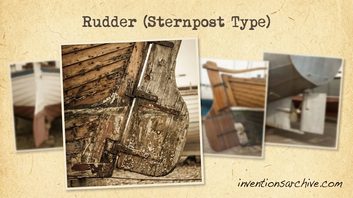
| Invention Name | Rudder (Sternpost Type) |
|---|---|
| Short Definition | A steering blade mounted on the vessel’s centerline at the stern, commonly hung from the sternpost and turned by a tiller or later steering gear. |
| Approximate Date or Period | China: first-century CE visual evidence for an axial stern-mounted rudder; Europe: late 12th century for the iron-hinged sternpost form. Based on surviving evidence |
| Geography | Early axial evidence in China; later pintle-and-gudgeon form in northern European waters. |
| Inventor or Source Culture | Anonymous and cumulative. No named individual can be verified as the sole inventor. Attribution varies |
| Category | Navigation, maritime transport, shipbuilding, and mechanical control. |
| Evidence Status | Early dates rely on pottery models, carved images, paintings, written descriptions, shipwreck fittings, and later archaeological interpretation. Approximate |
| Main Problem Solved | Steering larger or higher-sided vessels without relying only on a long side-mounted steering oar. |
| How It Works | The blade pivots around a near-vertical axis. Water flowing past the angled blade creates a sideways force that turns the vessel. |
| Technical Basis | Timber blade and sternpost; iron pintles, gudgeons, and straps in the European form; tiller, whipstaff, wheel, or powered steering gear above. |
| Early Uses | River craft, coastal vessels, cargo ships, and medieval northern European cogs. |
| Predecessors | Steering paddle, stern steering oar, twin steering oars, and quarter rudder. |
| Development Path | Steering oar → axial stern rudder → sternpost-hung rudder → wheel-operated rudder → powered and automated steering. |
| Main Variations | Chinese suspended or lifting rudder; unbalanced sternpost rudder; balanced rudder; semi-balanced rudder; spade rudder. |
| Importance |
|
| Surviving Evidence | Han-period ship models and images, medieval carvings and seals, iron rudder fittings, excavated ship remains, technical drawings, and museum models. |
| Related Inventions | Cog, sternpost, pintle and gudgeon, tiller, whipstaff, ship’s wheel, steering engine. |
| Modern Descendants | Balanced rudders, spade rudders, electro-hydraulic steering gear, autopilot, and integrated vessel-control systems. |
The sternpost rudder is a vertical steering blade placed at the rear centerline of a vessel. In its classic European form, the blade hangs from the sternpost on a set of metal pivots and sockets. The helmsman turns it through a tiller, a vertical whipstaff, a wheel-and-rope system, or powered machinery.
This arrangement changed more than the location of the steering surface. It linked steering gear, hull shape, stern structure, and the flow of water behind the vessel into one system. The idea remains recognizable in many modern rudders, even when the old wooden sternpost and visible iron hinges have been replaced by steel stocks, bearings, hydraulic rams, and electronic controls.
What a Sternpost Rudder Is
A sternpost rudder is defined by both its position and its support. It sits on or near the vessel’s longitudinal centerline at the stern. In the best-known medieval and early modern arrangement, its leading edge is attached to the sternpost by alternating metal fittings.
The pin-like fittings are called pintles. Their matching eyes or sockets are called gudgeons. Together they form a vertical hinge line. The rudder blade swings to port or starboard around that line, while a tiller or other steering mechanism applies the turning force.
The sternpost is structural; the rudder is movable. Confusing the two hides the central feature of the invention: a controlled blade could rotate behind a fixed part of the hull without requiring a large steering oar to project from one side.
The Steering Problem It Answered
Early vessels could be guided with paddles or large steering oars. A steering oar worked well on many river boats, galleys, and open craft. It could be placed over the stern or fastened near one quarter of the hull. Northern European vessels often carried a side-mounted quarter rudder on the starboard side.
The limits became more noticeable as some hulls grew broader, heavier, and higher above the water. A side steering oar had to be long enough to reach the water and strong enough to withstand the load. Its mounting, blade, and handle could become difficult to manage. It also occupied one side of the stern and could be exposed during docking, grounding, loading, or rough motion.
A centerline blade answered several of these problems:
- It used the water flowing directly behind the hull.
- It placed steering effort around a fixed vertical axis.
- It could be connected to mechanical advantage above deck.
- It suited straight or reinforced stern structures.
- It allowed steering arrangements to grow with vessel size.
The sternpost rudder did not make every earlier steering method obsolete. Steering oars remained useful on small craft and in shallow or fast-flowing water. Technologies overlap when each still answers a different need.
Earlier Steering Tools
Steering Paddles and Stern Oars
The simplest steering tool was a paddle used to push or redirect water. Larger boats used a dedicated steering oar with a broad blade. Some vessels carried a pair of steering oars near the stern, while others used one large oar.
A centrally placed stern oar could resemble a rudder in position, yet it was not necessarily a true hinged rudder. Its support might be a rope, notch, bracket, or transverse beam. It still behaved largely as an oar controlled by leverage through its shaft.
The Quarter Rudder
The quarter rudder was mounted near the after side of the hull. Viking-age ships provide well-known archaeological examples. The blade was held at the starboard quarter and controlled by a short handle set across its upper end.
This system was effective for long, flexible, double-ended hulls. It also explains the maritime word starboard, which is linked to the steering side. Yet the quarter rudder and the sternpost rudder are not merely two names for the same object. Their mounting geometry, load path, and relationship to hull form differ.
How the Origin Is Traced
Early Axial Stern Rudders in China
Chinese shipbuilding developed centerline stern steering long before the iron-hinged European type became common. A pottery ship model from the Han period is often cited as early visual evidence. Later Chinese vessels used large stern-mounted rudders that could be suspended, raised, or lowered to suit water depth.
Columbia University’s Asia for Educators material describes the Song-period sternpost rudder as an external steering device that could be adjusted vertically. This suited crowded ports, narrow waterways, and changing depth. It also places the rudder beside other Chinese shipbuilding features such as watertight bulkheads and sounding lines. [b]
The Chinese arrangement should not be imagined as an exact copy of the later European hinge system. Large junk rudders could be supported from above and guided by wooden structures rather than hung from a row of iron pintles and gudgeons. The shared idea is axial steering at the stern; the detailed engineering could differ.
The European Pintle-and-Gudgeon Form
In northern Europe, the sternpost rudder appears during a period when cargo vessels were changing in hull form and carrying capacity. Straight or steep stern structures offered a practical surface for a vertical hinge line. Iron straps and fittings could transfer loads between the blade and the hull.
The Kolding cog offers unusually direct archaeological evidence. Its oak hull has been dated by dendrochronology to about 1190, and the Maritime Stepping Stones database identifies it as the earliest known cog find with a stern rudder. The same record notes the transition from Viking-style rudders on older cogs to stern rudders on later examples. [c]
Images on seals, fonts, carvings, and manuscripts help fill the gaps left by incomplete wrecks. They show that the stern rudder was not a laboratory device waiting for adoption. By the later Middle Ages, it belonged to working cargo ships, cogs, hulks, and other vessels moving through European waters.
Transmission or Separate Development?
It is tempting to draw a straight arrow from China to Europe. The chronology makes contact or transmission possible, especially across long-distance trade networks. Yet a secure chain of documents, objects, and intermediate designs has not been established.
There is also a mechanical reason for caution. The Chinese suspended axial rudder and the European sternpost-hung rudder solved a similar steering problem with different support systems. European shipwrights may have encountered an outside concept, arrived at a similar answer locally, or combined both processes. The route remains unresolved.
How the Mechanism Works
A rudder does not push the stern sideways like a pole. When water flows past an angled rudder blade, pressure differs across its two faces. The blade produces a force with a sideways component. Because that force acts behind the vessel’s center of mass, it creates a turning moment, or yaw.
MIT marine hydrodynamics material treats rudders as lifting surfaces, alongside hydrofoils, keels, propeller blades, and sails. A lifting surface at an angle to the flow produces a force normal to that flow, while drag acts along it. This explains why a rudder becomes more effective when water moves past it and why excessive angle can add resistance or lead to separated flow. [d]
Main Working Parts
- Rudder blade: the submerged surface that redirects water force.
- Sternpost: the fixed stern member that supports the classic hinged type.
- Pintles: projecting pins attached to one side of the hinge pair.
- Gudgeons: matching eyes or sockets that receive the pintles.
- Rudder head or stock: the upper part that carries steering input.
- Tiller: a horizontal lever attached to the rudder head.
- Steering gear: later ropes, drums, wheels, gears, hydraulic rams, or electric controls.
The United States Naval History and Heritage Command describes a rudder as a steering device commonly formed as a flat metal or wooden slab hinged at its forward end to the stern or rudder post. It also defines the sternpost as the main vertical post on which the rudder is hung and the rudder stock as the shaft through which the rudder is turned. [e]
Why the Tiller Moves Opposite the Turn
With a direct tiller, pushing the tiller to port turns the rudder blade to starboard. The hydrodynamic force then pushes the stern toward port, so the bow turns toward starboard. This opposite movement later caused confusion when wheel commands, tiller orders, and rudder orders were used under different conventions.
The steering wheel did not change the basic blade action. It changed how human effort reached the rudder.
Materials and Construction Principle
Early sternpost rudders were mainly wooden structures reinforced with iron. The blade could be built from thick boards or shaped timbers held by crosspieces, straps, or bolts. The sternpost had to accept concentrated loads from the hinge fittings without splitting or loosening.
Iron pintles and gudgeons worked as a distributed hinge. Several pairs along the height of the rudder shared the load. This was more than simple attachment hardware: it created an axis that kept the rudder aligned while allowing rotation.
A National Maritime Museum component model preserves the mature arrangement in teaching form. The model separates the wooden sternpost and wooden rudder, shows brass fittings and multiple hinge positions, and marks the location of the tiller arm at the top. It demonstrates how the blade, fittings, post, and control lever functioned as connected parts. [f]
Later metal ships replaced much of the visible timber structure with stern frames, stocks, bearings, and plated rudder bodies. The central principle remained: a movable surface turns around a controlled axis at the stern.
Development Path
| Stage | Form | What Changed |
|---|---|---|
| Earlier Tool | Steering paddle or stern steering oar | Human force acted through a long shaft directly in the water. |
| Side-Mounted Form | Quarter rudder | A dedicated steering blade was fixed near one rear side of the hull. |
| Axial Form | Centerline stern rudder | Steering moved to the vessel’s centerline behind the hull. |
| European Sternpost Form | Pintle-and-gudgeon rudder | Iron hinge fittings attached the blade to a fixed sternpost. |
| Mechanical Control | Whipstaff and ship’s wheel | Levers, ropes, drums, and gearing increased control from deck. |
| Modern Form | Balanced blade with powered steering | Part of the blade area moved ahead of the stock to reduce steering torque. |
| Automated Descendant | Autopilot and integrated control | Sensors and control systems command the rudder to maintain or change course. |
Early Uses and Spread
In China, adjustable stern rudders served river, harbor, coastal, and seagoing vessels. Raising or lowering the blade helped crews match the steering surface to water depth and vessel load. A deep rudder could gain more effective area in open water, while a lifted blade reduced grounding risk in shallows.
In northern Europe, sternpost rudders became closely associated with the cog and other high-sided trading vessels. These ships carried bulk cargoes across the North Sea and Baltic. The rudder sat behind a steep stern structure and worked with a square sail, broad hull, and cargo-focused form.
Adoption was gradual rather than instant. Shipwrights had to alter stern geometry, place strong fittings, maintain a usable water flow around the blade, and arrange steering controls above it. Ports and repair yards also needed the skills to replace worn straps, pins, sockets, and timber.
By the later medieval and early modern periods, sternpost rudders appeared on many European merchant and seagoing sailing ships. Their use continued through the transition to larger multi-masted ships, oceanic voyages, and early steam propulsion.
Before and After
| Before the Sternpost Type | What Changed After Adoption |
|---|---|
| Large steering oars projected from the stern quarter or over the stern. | The steering blade could rotate around a fixed centerline axis. |
| Increasing freeboard demanded a longer and heavier steering oar. | Loads could be carried by several hinge fittings along the sternpost. |
| The steering device occupied one side and could be exposed during close handling. | The rudder sat behind the hull, though it still remained vulnerable to grounding and impact. |
| Direct manual leverage limited the size of blade one person could control. | Tillers, whipstaffs, wheels, and later powered gear multiplied human input. |
| Double-ended or curved stern forms suited quarter rudders. | Straighter and reinforced stern structures supported axial hinged rudders. |
| Steering performance depended heavily on the oar’s reach and mounting. | Rudder area, angle, balance, and water flow could be treated as design variables. |
| Side steering remained practical for many small craft. | Large cargo ships and later powered vessels gained a scalable steering arrangement. |
Main Types and Variations
| Type | Support and Position | Typical Feature |
|---|---|---|
| Suspended Chinese Stern Rudder | Centerline stern mounting, often supported or lifted from above | Vertical adjustment for different water depths. |
| Unbalanced Sternpost Rudder | Entire blade area lies behind the hinge line | Simple form, but high tiller or steering torque at larger loads. |
| Balanced Rudder | Part of the blade lies ahead of the turning axis | Water force on the forward area reduces the torque needed to turn it. |
| Semi-Balanced Rudder | Only part of the blade projects ahead of the stock | Combines reduced torque with structural support from the stern or horn. |
| Spade Rudder | Supported mainly by the rudder stock, without full sternpost hinging | Clean flow and good response, common on many modern vessels and yachts. |
| Flap Rudder | Main blade carries a movable trailing section | Produces greater turning effect at a given main rudder angle. |
What Changed in Ship Design
The Stern Became Part of the Steering System
The stern could no longer be treated only as the end of the hull. Its shape had to support the rudder and guide water toward it. The sternpost carried hinge loads, while the run of the hull influenced how evenly water reached the blade.
This encouraged stronger stern assemblies and closer coordination between shipwrights, metalworkers, and rigging specialists. Steering became an integrated shipbuilding problem.
Larger Steering Surfaces Became Manageable
A larger blade could generate more turning force, but it also required more control effort. Long tillers provided leverage. The whipstaff then allowed the helmsman to move a vertical lever connected to the tiller below. Later ship’s wheels used ropes or chains around a drum to move the tiller or quadrant.
These controls made it possible to operate rudders on ships where direct hand pressure on a short tiller would have been impractical. They also moved the steering position to a place with better shelter or visibility, depending on the vessel.
Steering Could Be Engineered and Measured
Once the rudder became a defined rotating surface, designers could compare blade area, aspect ratio, angle, hinge position, balance, and steering torque. The same line of thought led to modern naval architecture, model testing, powered steering, and maneuverability standards.
The sternpost type was therefore not the final rudder. It established a durable mechanical arrangement from which many later control surfaces developed.
Real Use at Sea
A helmsman used the rudder to hold a course, begin a turn, check a swing, align with a harbor entrance, avoid another vessel, or balance the steering effect of wind and sails. On a sailing ship, rudder action worked together with sail trim. A badly balanced sail plan could make the rudder carry a constant load and add drag.
Rudder response also depended on speed. With little water moving past the blade, steering force was weak. A vessel moving astern could respond differently because flow approached the rudder from the opposite direction. Waves, currents, shallow water, hull loading, and damage could further change handling.
The rudder was not only a directional switch. It was part of an operating relationship between speed, flow, hull form, propulsion, and human judgment.
Limits and Engineering Tradeoffs
- High steering torque: An unbalanced blade places all of its area behind the hinge line, demanding strong control gear.
- Structural stress: Pintles, gudgeons, straps, and stern timbers carry repeated and sometimes shock-like loads.
- Grounding damage: A deep blade can strike the bottom or submerged objects.
- Flow separation: At excessive angles, smooth flow can break away from the blade and reduce useful lift while increasing drag.
- Low-speed weakness: A rudder needs water flow; it may respond poorly when the vessel is nearly stopped.
- Maintenance: Wear, corrosion, loosened fastenings, marine growth, and timber decay can reduce reliability.
Later rudders addressed these limits with balanced area, stronger bearings, protected stocks, hydrodynamic sections, powered steering, and improved placement in the propeller stream.
Common Misunderstandings
“The Rudder Was Invented by One Known Person”
No reliable record names a sole inventor. The device emerged through changes in steering oars, hulls, stern structures, fittings, and control methods across long periods.
“The Chinese and European Rudders Were Identical”
They shared centerline stern steering, but their support systems could differ. Chinese rudders were often suspended or guided without the full row of iron pintle-and-gudgeon hinges typical of the European sternpost type.
“The First Surviving Image Proves the First Use”
An image proves that an idea was represented by a certain date. It does not prove that no earlier working example existed. Perishable steering gear has a poor survival rate.
“A Stern Rudder Automatically Made Any Ship Easy to Steer”
Effectiveness depended on hull shape, speed, blade area, water flow, steering leverage, and crew skill. Early unbalanced rudders could demand heavy effort.
“The Ship’s Wheel and the Rudder Are the Same Invention”
The rudder acts in the water. The wheel is a later control mechanism that transmits human input to the rudder through ropes, chains, gears, or powered systems.
Modern Descendants
Modern ships may use balanced, semi-balanced, horn-supported, or spade rudders made from welded steel. The blade is shaped more like a hydrodynamic foil than a flat wooden board. A rudder stock passes through bearings and connects to steering machinery inside the hull.
Hydraulic or electro-hydraulic gear moves the stock on large vessels. Position sensors report rudder angle, while bridge controls command course changes. Autopilot adds a feedback system that compares the vessel’s heading with the desired course and orders small corrections.
The International Maritime Organization’s GreenVoyage2050 material notes that automatic steering controls the rudder and that smoother, smaller rudder movements can reduce added drag and fuel demand. This is a modern expression of the same old problem: producing enough turning force without wasting motion or energy. [g]
Some vessels now use azimuthing propulsors, waterjets, or other combined steering-and-propulsion systems instead of a conventional sternpost rudder. Even so, the sternpost type remains an important ancestor of modern marine control surfaces.
Related Inventions
Frequently Asked Questions
Who invented the sternpost rudder?
No named inventor is securely documented. Early centerline stern rudders are represented in Chinese evidence, while the iron-hinged sternpost type appears in medieval northern European evidence. Both were products of cumulative shipbuilding practice.
When did the sternpost rudder appear in Europe?
Visual and archaeological evidence places the European pintle-and-gudgeon sternpost rudder in the 12th century. The Kolding cog, with hull timber dated to about 1190, is an early physical example.
How is a sternpost rudder different from a steering oar?
A steering oar acts through a long shaft and is supported like an oar or paddle. A sternpost rudder is a dedicated blade rotating on a vertical hinge or stock at the stern, with steering input applied through a tiller or other gear.
Why were pintles and gudgeons important?
They formed a strong, distributed hinge. Several fitting pairs kept the rudder aligned and transferred water loads into the sternpost while allowing the blade to rotate.
Is the sternpost rudder still used?
Traditional externally hinged forms remain on some wooden vessels and small craft. Modern ships more often use steel rudders supported by stocks, bearings, horns, or skegs, but these systems continue the centerline stern-steering principle.
Sources and Verification
- [a] Marine Rudders, Hydrofoils and Control Surfaces — Used to verify the development from steering oars to stern-mounted rudders, the early Chinese depiction, the 12th-century European evidence, and uncertainty around the Winchester carving. (Reliable because it is a specialist engineering history and design book from an academic publisher, written by University of Southampton maritime engineering scholars.)
- [b] Song Dynasty China: Shipbuilding and the Compass — Used to verify the Song-period description of adjustable stern-mounted rudders and their navigation setting. (Reliable because it is an educational resource hosted by Columbia University.)
- [c] Kolding Cog — Used to verify the dendrochronological date of about 1190 and the wreck’s status as an early cog with a stern rudder. (Reliable because MaSS is a maritime heritage database associated with the Cultural Heritage Agency of the Netherlands and cites Danish National Museum research.)
- [d] Marine Hydrodynamics Lecture 24A: Lifting Surfaces — Used to verify the hydrodynamic explanation of rudders as lifting surfaces that generate lift and drag in flowing water. (Reliable because it is marine hydrodynamics course material from the Massachusetts Institute of Technology.)
- [e] Nomenclature of Naval Vessels — Used to verify standard definitions for rudder, sternpost, and rudder stock. (Reliable because it is published by the U.S. Naval History and Heritage Command.)
- [f] Component Model; Rudder Model — Used to verify the physical relationship among the wooden sternpost, rudder, brass hinge fittings, and tiller position in a museum teaching model. (Reliable because it is a catalog record from the National Maritime Museum, Royal Museums Greenwich.)
- [g] Autopilot Adjustment and Use — Used to verify the modern relationship between automatic rudder control, rudder movement, drag, and fuel demand. (Reliable because it is published through an International Maritime Organization project.)

